83
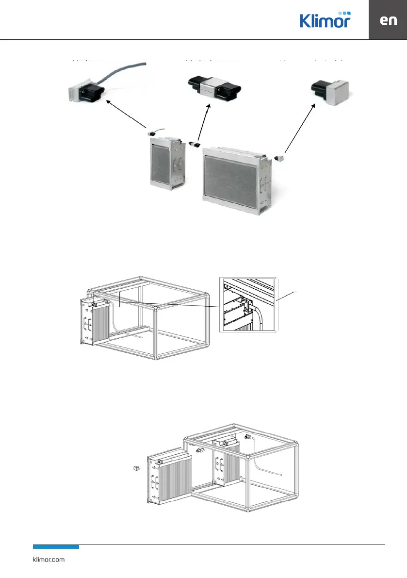
Fig. 51 Connection of power plugs
4.3.4 Installation of passive-active lters
Insert the power connector into the socket, remove the protective foil from the label on the back of the power connector
beforehand.
Fig. 52 Installation of the rst lter
Push the cell to the end. The power plug can lean against the back of the unit. Insert the lters one by one, adding an inter-
mediate connector between them / between each pair.
Fig. 53 Installation of the next lter
Insert the end plug into the end of the last lter and x it mechanically with the added screw.
(1) CA power connector
(2) CG adapter
(3) CT cover end connector
rear end
contact