7.15.3 Digital Outputs (X3A, X3B)
Technical characteristics
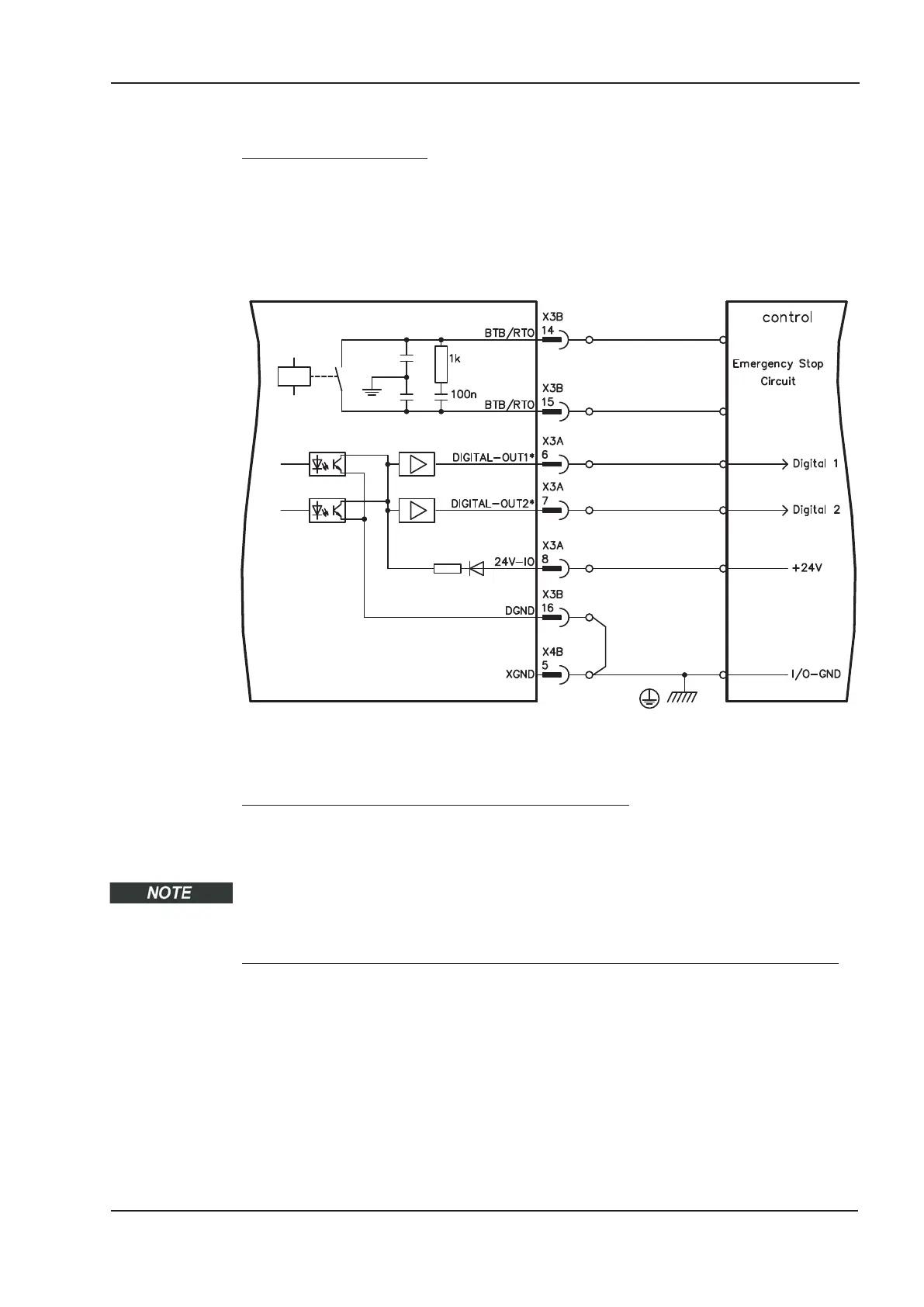
— Power supply at terminals X3A/8 (24V-IO) and X3B/16 (DGND)
— All digital outputs are floating
— 24V-IO : 20V DC … 30V DC
DIGITAL-OUT1 / 2 : PLC compatible (IEC 61131-2 type 1), max. 100mA
BTB/RTO : Relay output, max. 30V DC or 42V AC, 0.5A
— Update rate : 250 µs
* DIGITAL-OUT 1 and 2 must be defined as outputs using the setup software (“Digital I/O” screen
page).
Ready-to-operate contact BTB/RTO (X3B/14, X3B/15)
Operational readiness (terminals X3B/14 and X3B/15 ) is signaled by a floating relay
contact. The contact is closed when the servo amplifier is ready for operation, and the
signal is not influenced by the enable signal, the I²t-limit, or the brake threshold.
All faults cause the BTB/RTO contact to open and the output stage to be switched off (if
the BTB/RTO contact is open, the output stage is inhibited -> no power output). Error
messages are listed on page 122.
Programmable digital outputs DIGITAL-OUT 1 and DIGITAL-OUT 2 (X3A/6,X3A/7):
Pins 6 and 7 on X3A can be used as either inputs or outputs. Choose the function you
require in the setup software (OxMODE). The outputs are floating outputs, so the 24 V
switching voltage must be provided by an external supply.
If they are programmed as digital outputs, messages from pre-programmed functions sto-
red in the servo amplifier can be output here.
A list of these pre-programmed functions can be found on the “I/O digital” screen page of
our setup software DRIVEGUI.EXE.
If an output is to be freshly assigned to a pre-programmed function, then the parameter
set must be saved in the EEPROM of the servo amplifier and a reset has to be carried out
(with the amplifier setup software for example).
S701x2-S724x2 Instructions Manual 101
Kollmorgen 07/2014 Electrical installation
S700
 Loading...


