9.3 Expansion cards for slot 3
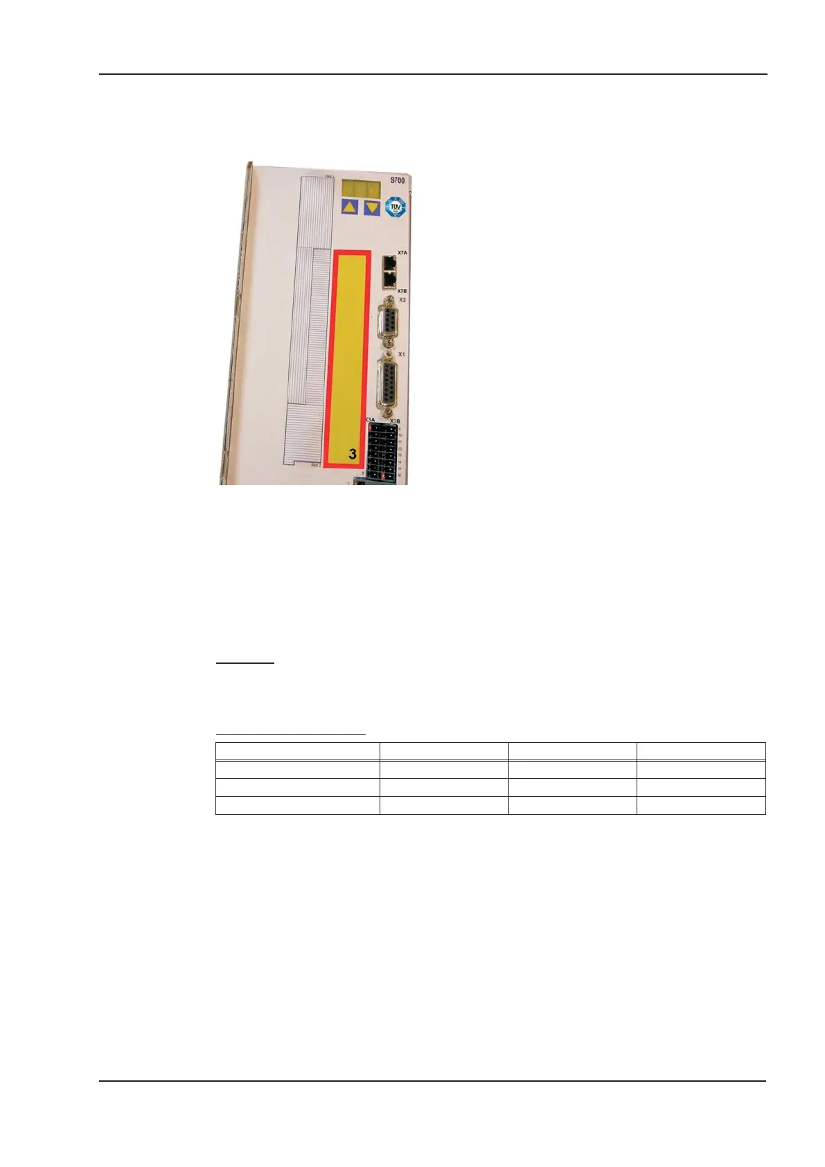
9.3.1 Guide to installation of expansion cards in slot 3
The method of installing the expansion card in slot 3 is
the same as that described for slot 1 (see p.125).
l
Remove the area of the front film colored yellow
(labeled slot 3).
l
Lever out the cover plates under the film.
l
Remove the small PCB (STO Bridge) which is
plugged into slot. Use suitable pliers.
l
Push the expansion card into the slot.
l
Use the screws provided to fasten the front plate of
the expansion card in place.
9.3.2 Option "F2", controlled Fan
To reduce noise emission the servo amplifiers can be ordered with the built-in option card
F2. This option cannot be built-in later. The F2 option card fits to slot2 or 3 (see part num-
ber scheme on p.24).
Function
The fan is switched on and off or runs with 50% rated speed depending on temperature
and brake power. That reduces the average noise emission.
Switching temperature
Monitoring Fan off Fan 50% Fan on
Internal temperature < 55°C ~ 58°C > 65°C
Heat sink temperature < 60°C ~ 65°C > 75°C
Brake resistor (internal) < 20W ~ 30W > 45W
9.3.3 Expansion cards "PosI/O" & "PosI/O-Monitor"
The “PosI/O” and "PosI/O-Monitor" expansion cards can be pushed into slot 2 or 3. The
expansion cards cannot be combined and the use of only one slot in time is allowed.
A detailed description of the interfaces can be found from page 142.
S701x2-S724x2 Instructions Manual 151
Kollmorgen 07/2014 Expansions
Boundary of SLOT3
 Loading...


