CP308 CP308-MEDIA
ID 1027-4487, Rev. 3.0 Page B - 9
P R E L I M I N A R Y
B.6 Module Interfaces (Front Panel and Onboard)
B.6.1 DisplayPort Interfaces
The CP308-MEDIA provides two DisplayPort interfaces (digital audio/video display interfaces)
implemented as two 20-pin DisplayPort connectors on the front panel for connection to moni-
tors with DisplayPort interfaces. Additionally, the GS45 chipset provides a DisplayPort interop-
erability support for DVI/HDMI displays through a passive cable adapter. Monitors with an
analog VGA interface can also be connected to the DisplayPort connectors via an appropriate
active adapter.
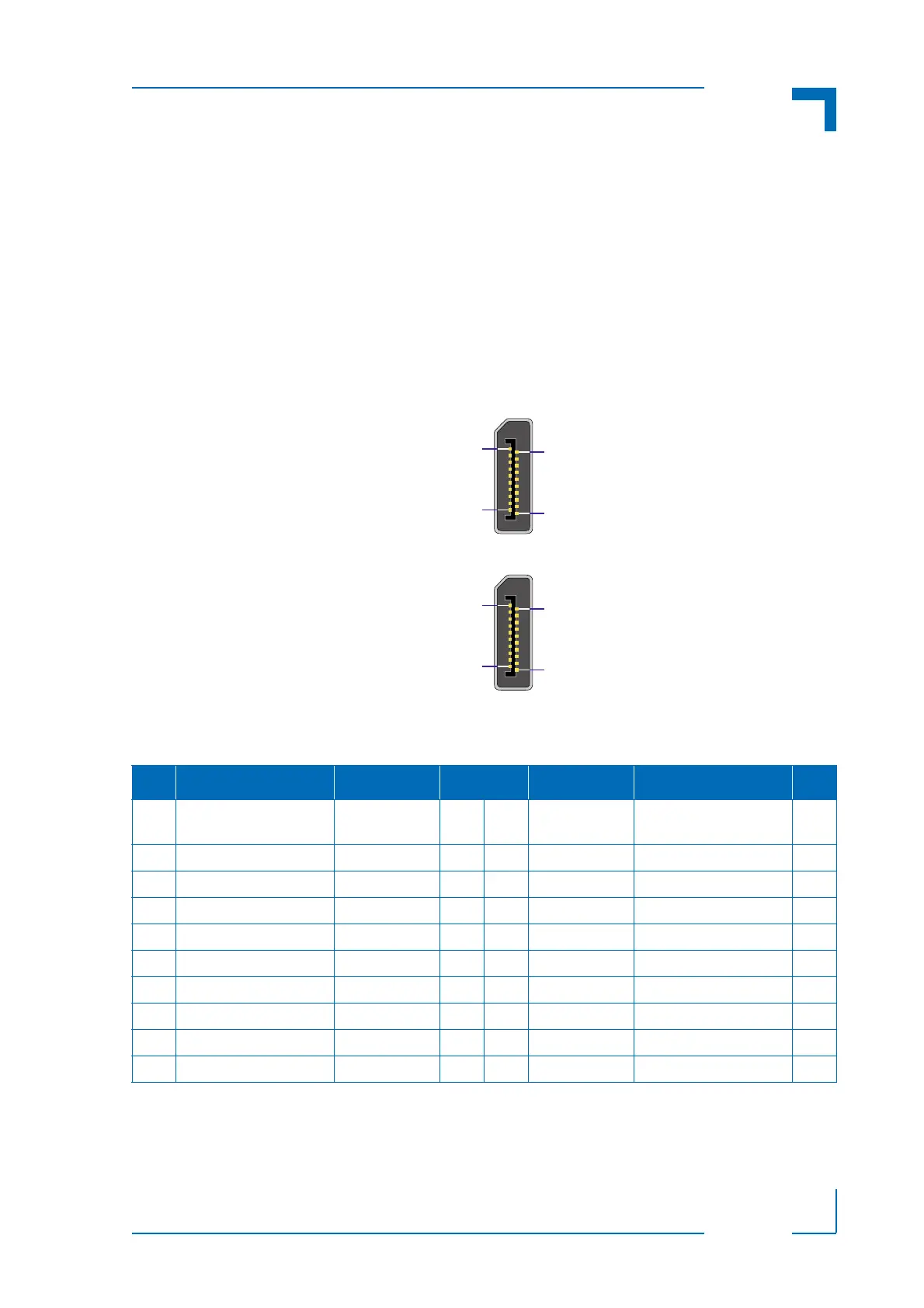
The following figure illustrates the DisplayPort connectors J2 and J4.
Figure B-5: DisplayPort Connectors J2 and J4
The following table indicates the pinout of the DisplayPort connectors J2 and J4.
* To select DP, the signal HDMI_SEL must be connected to Ground.
To select HDMI/DVI, the signal HDMI_SEL must be connected to +3.3V or +5V via a 100 kΩ
resistor.
Table B-2: DisplayPort Connectors J2 and J4 Pinout
I/O FUNCTION SIGNAL PIN SIGNAL FUNCTION I/O
-- Power 3.3 V,
0.5 A fuse protection
PWR 20 19 RETURN Return for power --
I Hot Plug Detect HP_DET 18 17 AUX_CH- Auxiliary Channel- I/O
-- Signal ground GND 16 15 AUX_CH+ Auxiliary Channel+ I/O
-- Signal ground GND 14 13 HDMI_SEL* DP/HDMI/DVI Select I
-- Signal ground GND 12 11 ML(3)- Data Lane3- O
O Data Lane3+ ML(3)+ 10 9 GND Signal ground --
O Data Lane2- ML(2)- 8 7 ML(2)+ Data Lane2+ O
-- Signal ground GND 6 5 ML(1)- Data Lane1- O
O Data Lane1+ ML(1)+ 4 3 ML(0)- Data Lane0- O
-- Signal ground GND 2 1 ML(0)+ Data Lane0+ O