CP308 Functional Description
ID 1027-4487, Rev. 3.0 Page 2 - 15
P R E L I M I N A R Y
2.3.6 Gigabit Ethernet
The CP308 board includes two 10Base-T/100Base-TX/
1000Base-T Ethernet ports based on two Intel® 82574L
Gigabit Ethernet controllers, which are connected to the
x1 PCI Express interfaces of the ICH9M-SFF.
The Intel® 82574L Gigabit Ethernet Controller’s archi-
tecture is optimized to deliver high performance with
the lowest power consumption. The controller's archi-
tecture includes independent transmit and receive
queues and a PCI Express interface that maximizes the
use of bursts for efficient bus usage.
The Boot-from-LAN and Wake-on-LAN features are
supported. Wake-on-LAN is available on all Ethernet interfaces. After an operating system
shutdown, a 1000Base-T Gigabit connection is automatically reduced to 100 Mbit or 10 Mbit
operation and the Ethernet controller waits to receive a broadcast or unicast packet with an ex-
plicit data pattern to assert a signal or a PME message to wake up the system. If the main pow-
er is switched off after an OS shutdown, a 5V standby supply must be provided over the J2 rear
I/O CompactPCI connector to continue powering the Wake-on-LAN relevant devices.
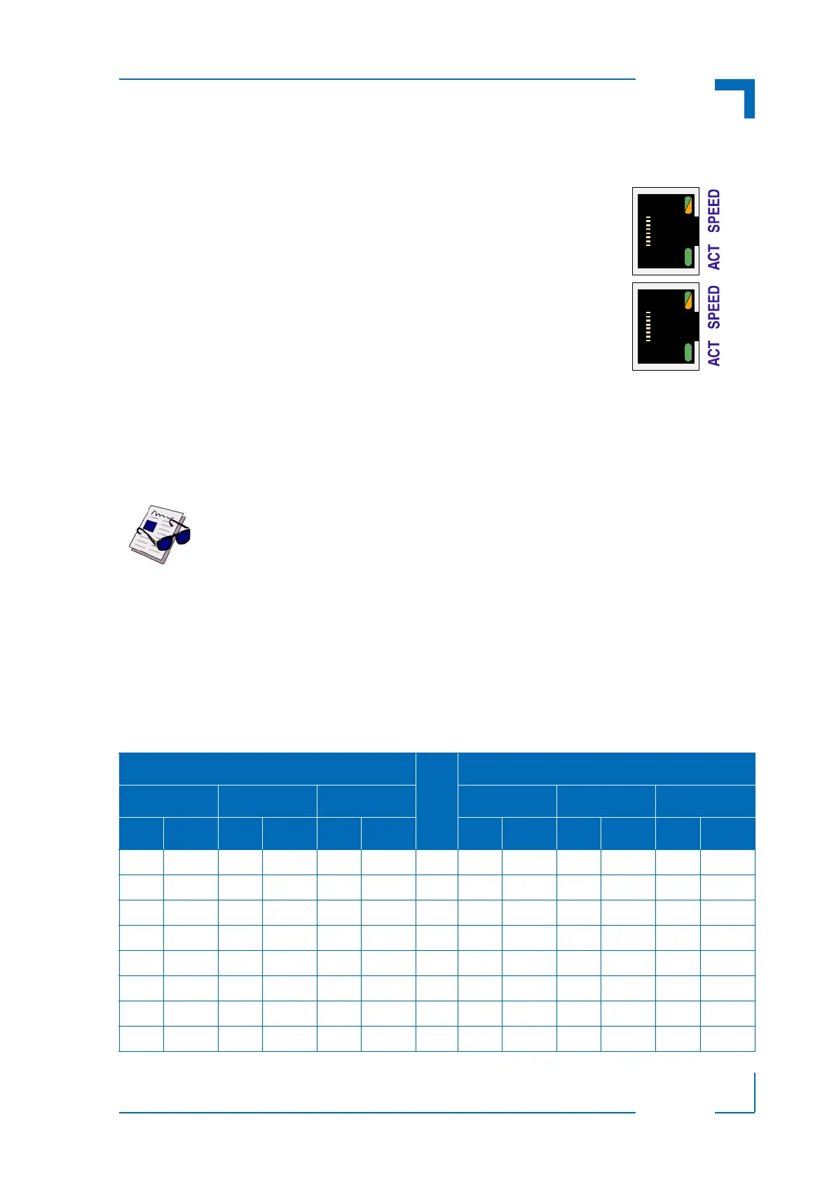
The Ethernet connectors are realized as RJ-45 connectors. The interfaces provide automatic
detection and switching between 10Base-T, 100Base-TX and 1000Base-T data transmission
(Auto-Negotiation). Auto-wire switching for crossed cables is also supported (Auto-MDI/X).
RJ-45 Connector J6A/B Pinout
The J6A/B connector supplies the 10Base-T, 100Base-TX and 1000Base-T interfaces to the
Ethernet controller.
Note ...
The Ethernet transmission can operate effectively using a CAT5 cable with a
maximum length of 100 m.
Table 2-12: Pinout of J6A/B Based on the Implementation
MDI / STANDARD ETHERNET CABLE
PIN
MDIX / CROSSED ETHERNET CABLE
10BASE-T 100BASE-TX 1000BASE-T 10BASE-T 100BASE-TX 1000BASE-T
I/O SIGNAL I/O SIGNAL I/O SIGNAL I/O SIGNAL I/O SIGNAL I/O SIGNAL
O TX+ O TX+ I/O BI_DA+ 1 I RX+ I RX+ I/O BI_DB+
O TX- O TX- I/O BI_DA- 2 I RX- I RX- I/O BI_DB-
I RX+ I RX+ I/O BI_DB+ 3 O TX+ O TX+ I/O BI_DA+
----I/OBI_DC+4----I/OBI_DD+
----I/OBI_DC-5----I/OBI_DD-
I RX- I RX- I/O BI_DB- 6 O TX- O TX- I/O BI_DA-
----I/OBI_DD+7----I/OBI_DC+
----I/OBI_DD-8----I/OBI_DC-
Figure 2-3: Dual Gigabit Ethernet
Connector J6A/B