CP308 Configuration
ID 1027-4487, Rev. 3.0 Page 4 - 3
P R E L I M I N A R Y
4. Configuration
4.1 DIP Switch Configuration
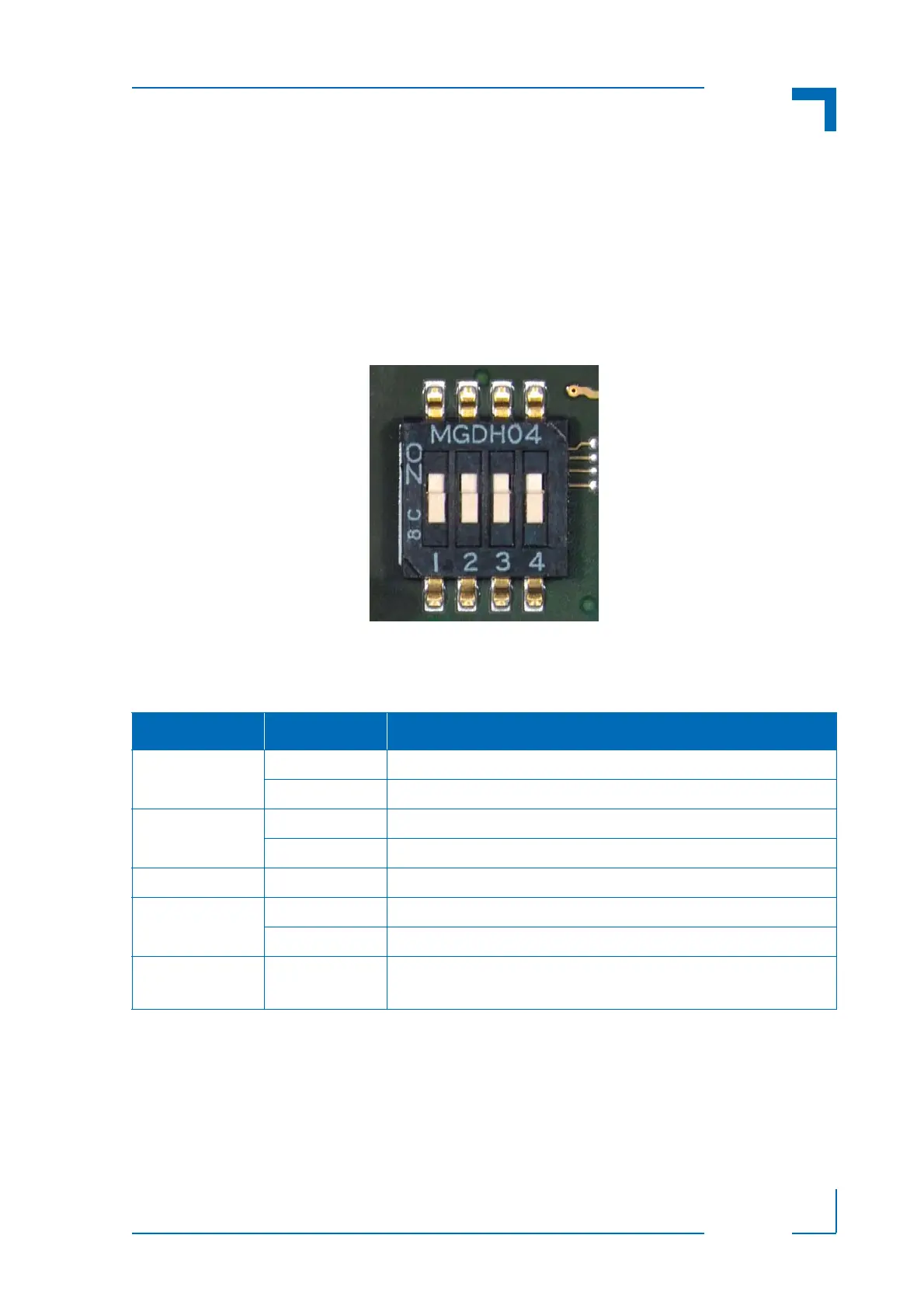
The DIP switch consists of four switches for board configuration: switch 1 for the SPI Flash con-
figuration, switch 2 for the uEFI BIOS configuration, switch 3 reserved for future use, and switch
4 for reset configuration (PCB index 01)/reserved for future use (PCB index 00).
Figure 4-1: DIP Switch SW1
The following table indicates the functionality of the four switches integrated in the DIP switch.
The default setting is indicated by using italic bold.
Table 4-1: DIP Switch SW1 Functionality
SWITCH SETTING FUNCTIONALITY
1 OFF Normal boot from the primary SPI Flash
ON Normal boot from the secondary SPI Flash
2 OFF Normal boot using the uEFI BIOS settings
ON Clear the uEFI BIOS settings and use the default values
3 -- Reserved for future use
4
(PCB index: 01)
OFF Edge-sensitive reset configuration (ICH9M-SFF reset implementation)
ON Level-sensitive reset configuration (FPGA PGOOD logic to ICH9M-SFF)
4
(PCB index: 00)
-- Reserved for future use