Functional Description CP308
Page 2 - 20 ID 1027-4487, Rev. 3.0
P R E L I M I N A R Y
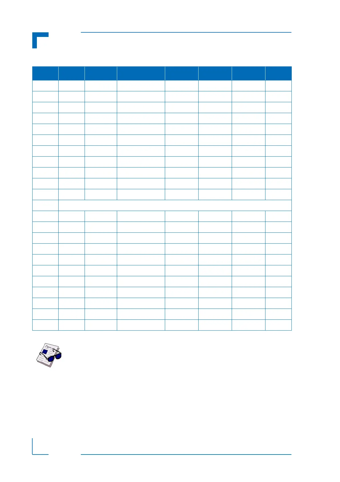
Table 2-15: CompactPCI Bus Connector J1 Peripheral Slot Pinout
PIN Z A B C D E F
25 NC 5V * * 3.3V 5V GND
24 NC * 5V V(I/O) * * GND
23 NC 3.3V * * 5V * GND
22 NC * GND 3.3V * * GND
21 NC 3.3V * * * * GND
20 NC * GND V(I/O) * * GND
19 NC 3.3V * * GND * GND
18 NC * GND 3.3V * * GND
17 NC 3.3V IPMB SCL IPMB SDA GND * GND
16 NC * * V(I/O) * * GND
15 NC 3.3V * * BDSEL# * GND
14-12 Key Area
11 NC * * * GND * GND
10 NC * GND 3.3V * * GND
9 NC * NC * GND * GND
8NC* GND V(I/O)* * GND
7 NC * * * GND * GND
6 NC * CPCI_PRESENT# 3.3V * * GND
5NCNC NC RST#**GND * GND
4 NC IPMB PWR HEALTHY# V(I/O) RSV RSV GND
3NC* * * 5V * GND
2NCTCK 5V TMS NC TDI GND
1 NC 5V NC TRST# NC 5V GND
Note ...
A * indicates that the signal normally present at this pin is disconnected from the
CompactPCI bus when the CP308 is inserted in a peripheral slot.
** When the CP308 is inserted in a peripheral slot, the function of the RST# sig-
nal can be enabled or disabled.