48
3
© 2018 KOSTAL Solar Electric GmbH
Installation
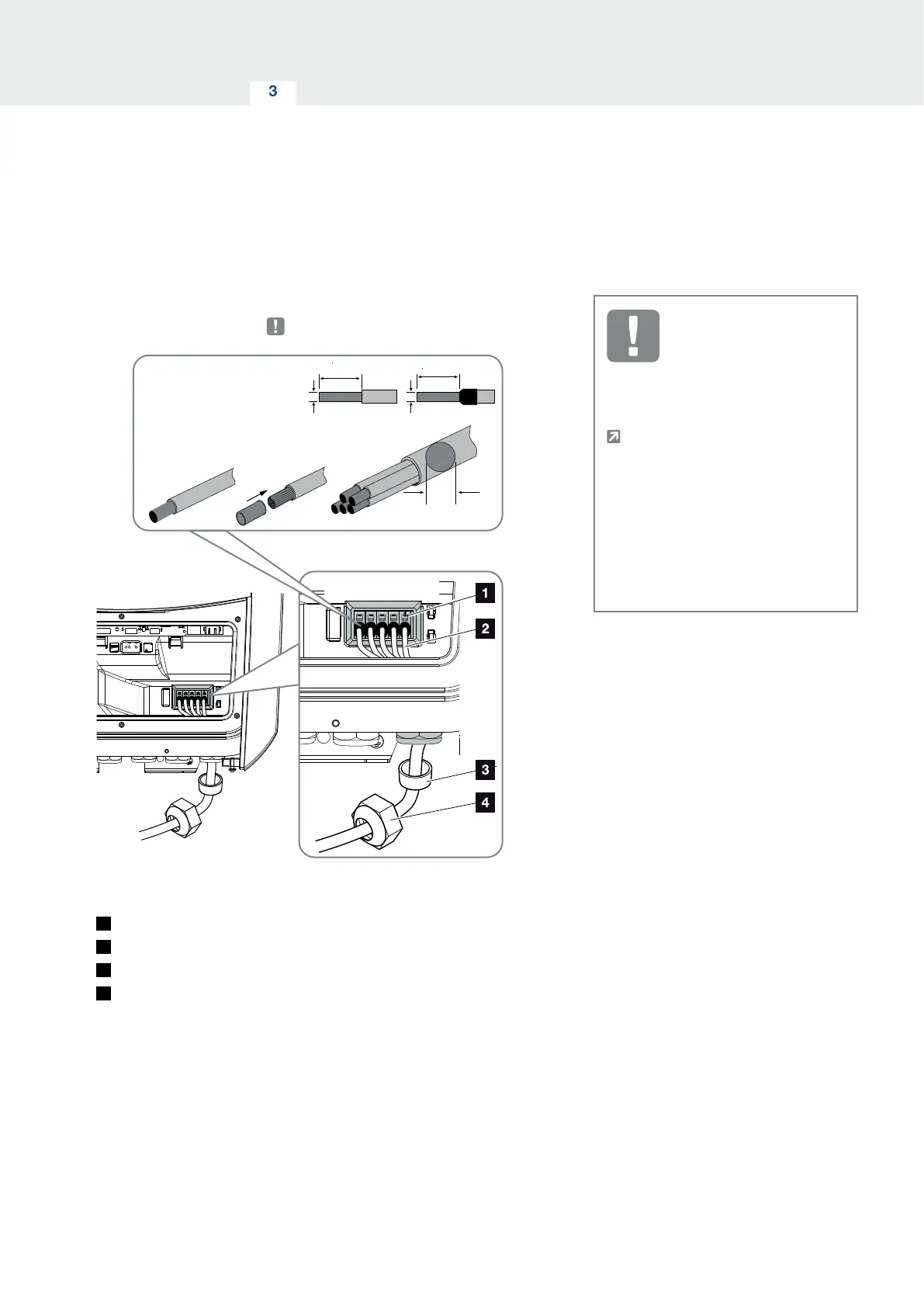
6. Correctly lay the mains cable from the power distrib-
utor to the inverter.
8 Nm
L1 L2 L3 N
L1 L2 L3 N
L1|L2|L3|N|PE
max. 10-17 mm
4.2 = 1,5 - 6 mm² 18 mm
5.5 = 1,5 - 6 mm² 18 mm
7.0 = 2,5 - 6 mm² 18 mm
8.5 = 2,5 - 6 mm² 18 mm
10 = 4 - 6 mm² 18 mm
NYM-J
NYY-J
H05../H07
RN-F
A
A
B
A
B
B
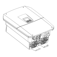
Fig. 22: Connecting mains cable to the inverter
1
AC terminal
2
Mains cable
3
Sealing ring
4
Union nut
7. Insert mains cable into the inverter and seal with
sealing ring and union nut. Tighten union nut to the
prescribed torque. Torques: 8 Nm (M25).
8. When threaded connections are not used, leave the
sealing ring in the threaded connections.
IMPORTANT
INFORMATION
See the "Technical Data" chap-
ter for the dimensioning of the
required AC line circuit breaker.
Ch. 11.1
Single-wire cables (type NYY-J or
NYM-J) without core end sleeves
can be used with the AC terminal.
When using cables with fine wires
(type H05../H07RN-F), core end
sleeves should be used. Ensure
that there is a contact surface of
18 mm.
 Loading...