3-104 BA 348-01 * 2.0 * 34801b340.fm
3 Operation
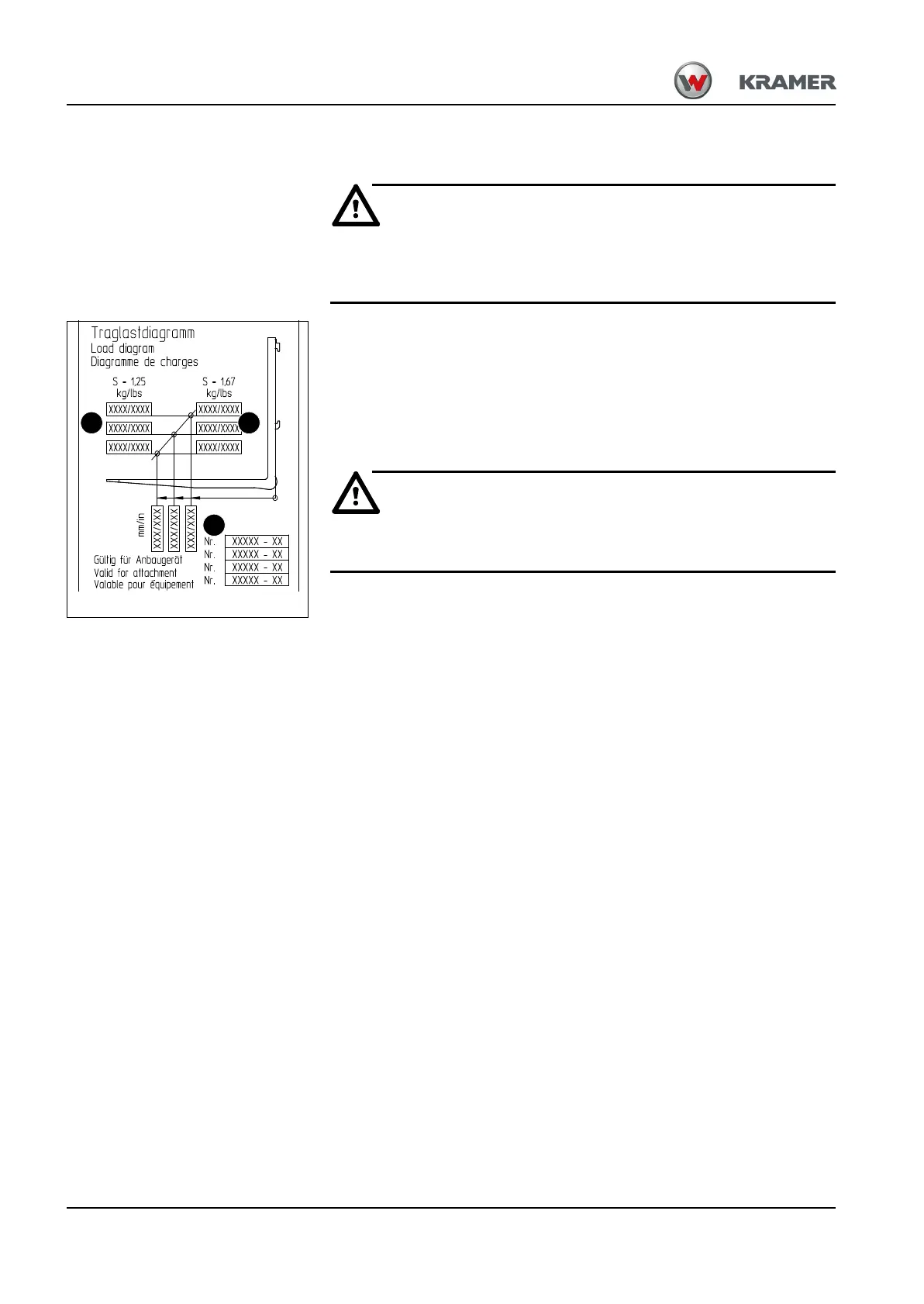
Load diagram for pallet forks
In order to avoid risk of accidents and damage to the machine, observe the
load diagram under all circumstances during fork lift operation!
The load diagram is located at the rear of the loader unit bulkhead.
The framed row of numbers A on the left states the maximum load for applications on level
ground (stability s = 1.25)
The framed row of numbers B on the right states the maximum load for off-road applications
(stability s = 1.67).
The maximum load is a function of the distance (load distance) between the load centre
and the fork frame C (lower row of figures). Take this into account also when using fork
arm extensions!
Do not exceed the maximum loads stated, otherwise machine stability is no
longer ensured.
Example:
Off-road =>safety factorS = 1.67 (framed row of figures on the right B)
Load distance = 400 mm (vertical centre line)
The maximum load C amounts to xxxx! (Intersection of the middle vertical line with the
slanting line (load curve))
A A
C
B
Fig. 141 : Load diagram