Settings
255
Pos: 51.22 /Übersc hriften/Überschri ften 3/A-E/A/Andrüc krolle einstellen @ 33\mod_1 253783433270_78.d ocx @ 317295 @ 3 @ 1
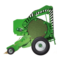
17.1.4 Adjusting the idler roller
Pos: 51.23 /BA/Bedienun g /Rundballenpresse/ Bild Andruckrol le @ 33\mod_1253784658363 _78.docx @ 317341 @ @ 1
VP-3-014
2
3
Fig. 206
Pos: 51.24 /BA/Bedienun g /Rundballenpresse/ Andrückrolle ein stellen @ 33\mod_1253783 906629_78.doc x @ 317316 @ @ 1
If the twine is not being drawn in correctly at the start, the pressure of the idler roller can be
increased with the spring (2):
Right-hand side
1. Detach spring (2).
2. Remove the screw (3) and mount it in one of the top holes.
3. Reattach the spring (2).
Left-hand side
Pressure can be increased by hooking the spring into the holes.
Pos: 51.25 /Übersc hriften/Überschri ften 3/P-T/SSensor eins tellen @ 33\mod_125379 2942785_78.docx @ 317601 @ 3 @ 1
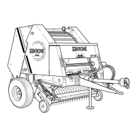
17.1.5 Adjusting the sensor
Pos: 51.26 /BA/Einste llungen/Rundball enpresse/Bild Einste llung Sensor @ 33\mod_12 53793123473_78.doc x @ 317697 @ @ 1
4
1
RBV00021
Fig. 207
Pos: 51.27 /BA/Einste llungen/Rundball enpresse/Einste llung Sensor @ 33\mod_1253793 023160_78.doc x @ 317622 @ @ 1
To allow for the twine not always starting or being cut off in the same place, the sensor (1) can
be moved left or right.
1. Loosen the screw (4).
2. Move the sensor support (1).
3. Retighten the screw.
Pos: 51.28 /Layout Module /---------------Seitenumbruch---------------- @ 0\mod_1196175311226_0. docx @ 4165 @ @ 1
 Loading...