Table of Contents
4
3.6 Safety stickers on the machine ........................................................................................................ 31
3.6.1 Position and meaning of the safety stickers on the machine .................................................... 31
3.6.2 Re-Ordering Safety Labels and Information Labels .................................................................. 48
3.6.3 Attaching Safety Labels and Information Labels ...................................................................... 48
3.6.4 Contact ...................................................................................................................................... 48
3.7 Safety Equipment ............................................................................................................................. 49
3.7.1 Parking Brake ............................................................................................................................ 49
3.7.2 Attaching the safety cable ......................................................................................................... 50
3.7.3 Parking Support ........................................................................................................................ 51
3.7.4 Wheel chocks ............................................................................................................................ 52
3.7.5 Stop Points ................................................................................................................................ 53
3.7.6 Shut-off valve for tailgate .......................................................................................................... 54
3.7.7 Step for working on the linkage ................................................................................................. 55
4 Data memory ......................................................................................................................................... 56
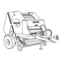
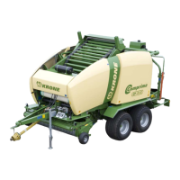
5 Machine Description ............................................................................................................................ 58
5.1 Machine overview ............................................................................................................................. 58
5.2 Identification Plate ............................................................................................................................ 59
5.3 Information Required for Questions and Orders .............................................................................. 59
6 Technical data....................................................................................................................................... 60
6.1 Hydraulic Connections ..................................................................................................................... 65
6.2 Consumables ................................................................................................................................... 65
6.3 Ambient Temperature ...................................................................................................................... 66
7 Commissioning..................................................................................................................................... 67
7.1 Before initial start-up ........................................................................................................................ 67
7.2 Assembling the bale ejector ............................................................................................................. 73
7.3 Adjusting the drawbar height ............................................................................................................ 78
7.4 PTO shaft ......................................................................................................................................... 81
7.4.1 Mounting the protective cap for the universal shaft of the tractor ............................................. 81
7.4.2 Mounting the universal shaft at the machine ............................................................................ 82
7.4.3 Length adjustment..................................................................................................................... 84
7.5 Mounting the hose and cable support .............................................................................................. 85
7.6 Preparing the wrapping material brake ............................................................................................ 85
7.7 Attaching the Triangle Spotlights ..................................................................................................... 86
7.8 Checking/setting the tyre pressure ................................................................................................... 86
8 Start-up .................................................................................................................................................. 87
8.1 Connect the machine to the tractor .................................................................................................. 88
8.2 Hydraulics ......................................................................................................................................... 89
8.2.1 Special Safety Instructions ........................................................................................................ 89
8.2.2 Connecting the hydraulic lines .................................................................................................. 90
8.3 Hydraulic brake (Export) .................................................................................................................. 92
8.4 Hydraulic brake (auxiliary brake) ...................................................................................................... 92
8.4.1 Install the PTO shaft.................................................................................................................. 93
8.5 Compressed Air Connections for the Compressed Air Brake .......................................................... 95
8.6 Electrical connections ...................................................................................................................... 96
8.7 Connecting KRONE BETA II Terminal ............................................................................................. 97
8.8 Connecting KRONE ISOBUS-Terminal ........................................................................................... 99
8.9 Connecting External ISOBUS-Terminal ......................................................................................... 102
8.10 Connecting the Joystick ................................................................................................................. 103
 Loading...