KW Aufzugstechnik GmbH OPERATING MANUAL DAVID-613
DAVID-D613-V125-E 13.04.2021 Page - 42 -
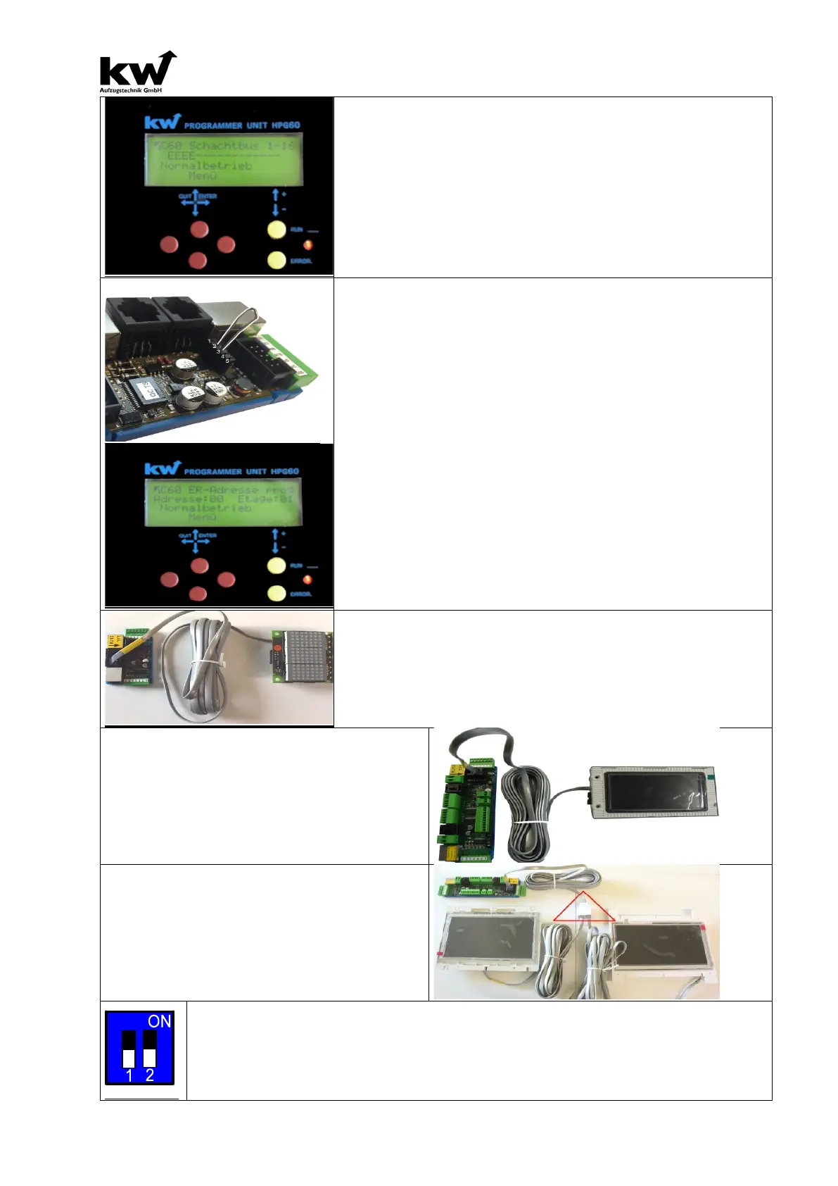
When the ER-
2013/2014 connected with bus line and the control is
active, the green LED is blinking. In short circuit on the busline or mal-
function expires or shine the LED. You can control the Remote Station
in Menu C6 Modul Monitor/ Remote Station ER01-
Station ER 17-32.
For every remote station which function is ok, there will be shown an
„E“ in the display of the HPG-60. From left to right, you can see in
the display all remote stations from the first floor to the highest floor
which are recognized in the system.
All ER-2014 preset for the individual floors. The bottom floor has al-
ways marked “Floor 01”. The setting of floors is no longer adress
switch on the Remote Station, like ER-2005, but by setting software.
1. STEP: Switch off the controller ( Main Switch Q1, and Fuses
F6 & F7 switch off ).
2. STEP: The Remote Station programmed with the RJ-
with the central unit. All other Remote Stations may not be connected.
3. STEP: It must be set a jumper on the 5-pin socket Print be-
tween pins 2 and 3 (-> see picture left). Then, the system can be put
under power (main switch Q1, Q6 is switched on).
4. STEPt: You can regulate the parameter “Remote Station Adress
programming” in menu C6 Modul Monitor. The ER-
adress with the selection of the number of floors. (01-
ER-2014 can be installed in the corresponding floor.
TERMINAL: MATRIX-INDICATOR TYPE ANZ-xx
The connection of the Matrix-indicator of type ANZ-XX (ANZ-22,
ANZ-32, ANZ.-33, ANZ-52 & ANZ-53) takes place on the black RJ-
12 jack with the black RJ-12 cable.
Don’t put the RJ-12 in the silber RJ-45 jack!
Connection of a TFT-Displays at a ER-
2014
The connection of TFT displays is done by the yel-
low RJ-12 jack with the included RJ-12 cable.
The RJ-12 cable is not allowed to be plugged
the RJ-45 jack silver or in one of the two RJ12 sock-
Connection of several TFT-Displays at
an ER-2014
Several TFT displays can be operated at a terminal
by means of a RJ-12 splitter.
This is necessary in elevator installations with sev-
eral door sides, or in elevator groups.
On the remote station ER-2014 is a 2-pole DIL switch for activating functions.
1. Switch-
1 can be used to switch on termination. The termination is only to be activated for
the last floor computer on the bus.
2.The passive bus is activated on switch-
2. A passive bus can only output information, e.g.
Arrows and cabin stand. It therefore operates in the same address space as the Shaftbus-1.