KW Aufzugstechnik GmbH OPERATING MANUAL DAVID-613
DAVID-D613-V125-E 13.04.2021 Page - 69 -
4. FUNCTION DESCRIPTION
4.1 GENERAL WORKING WITH THE HPG60 & NAVIGATION
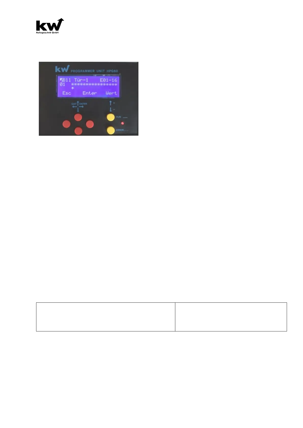
The handheld programming device HPG60
has 6 buttons, a four-line LCD display, a
red light-emitting diode, and a 9-pin RS232
interface.
The supplied serial cable is to be plugged
into the 9-
pin interface socket on the
HPG60, as well as on the central computer,
car computer or interior panel computer in
the 9-pin interface socket.
If the access authorization of the HPG60 matches that of the microprocessor system,
"A1 system parameters" appears in the display.
The six buttons are divided into two groups. On the one hand, the four red buttons
form a two-axis control, i.e. the upper and lower keys can be used to step through the
individual menu items.
There are eight main menus, between which you can scroll from one to eight and back
using the arrow up and arrow down keys. The individual parameters can be selected
in the menu using the left or right red button. The value of the parameter appears on
the right.
If the VALUE of the parameter is to be changed, the two yellow buttons come into
action. The value is increased with the upper yellow button, minimized with the lower
one.
The parameter value is shown flashing. If the new value is to be saved, press the right
red key (ENTER).
If the new value is to be discarded, the left red key can be pressed (ESCAPE).
The valid key assignment is shown in the fourth line of the display. Parameters can
only be changed when the device is at a standstill and without entering a command.
The red LED lights up constantly during operation. If an error occurs, it starts to flash.
The display is composed as follows:
Menu Element Parameter Value e.g.
Shaft Door Bounce Suppression 100 ms
Error 41: Operating Time Surveillance