KW Aufzugstechnik GmbH OPERATING MANUAL DAVID-613
DAVID-D613-V125-E 13.04.2021 Page - 43 -
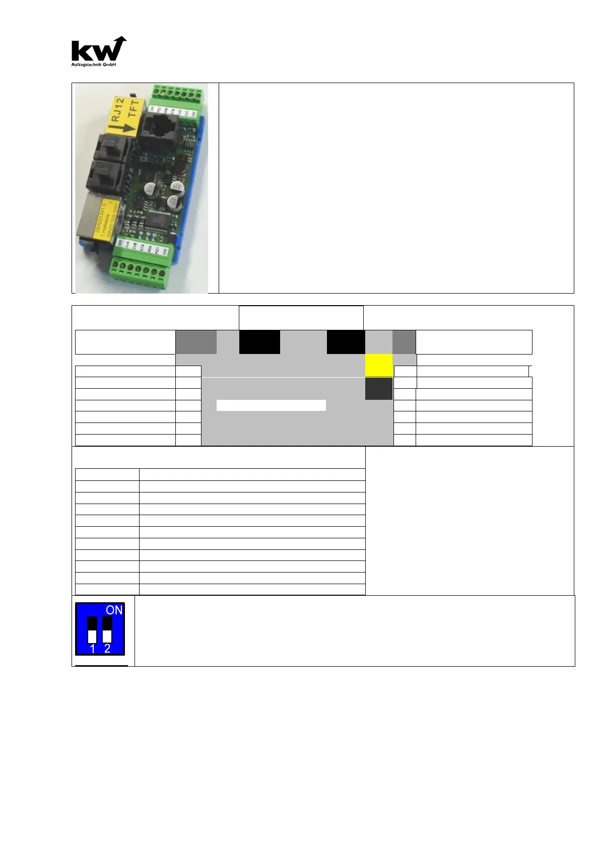
2.12 DESCRIPTION REMOTE STATION ER-2013
The remote station ER-2013 provides 8 inputs and outputs, including 6 free
inputs and outputs. There are 2 piece-outputs for the call messaging of bus-
matrix-indicator.
The remote station has all necessary call-channels and arrow-outputs (even for
selective door-controlling)
The installation of Remote Station is in the standard shaft cable channel 90x40.
You combinate the Bus and Power only with blue connection cable RJ-45-
Cable.
The lower 7-pin plug with the call-
messaging 2xA & 2xB is responsible for the
Door 1, the upper plug with 2xC & 2xD for the Door 2.
The two 10 pin ribbon cable connectors have the same functional assignments,
such as the green plug.
The matrix-indicator with RJ-12 cable are to put in the 2 black jacks.
The yellow marked RJ-12 jack for high-quality TFT graphic displays with KW-
bus connection.
RJ12-Bus Grey LEDMatrix
Bus- RJ-45 Blue
Bus- RJ-45 Blue
Free: for example Landing Call Door 2 Up at selective D
Free: for example Landing Call Door 2 Down at selectiv
Free: for example Level Arrow Door 1 Up
Free: for example Level Arrow Door 1 Down
Free: for example Level Arrow Door 2 Up
Free: for example Level Arrow Door 2 Down
On the remote station ER-2014 is a 2-pole DIL switch for activating functions.
1. Switch-
1 can be used to switch on termination. The termination is only to be activated for the
last floor computer on the bus.
2.The passive bus is activated on switch-2. A passive bus can only output information, e.g. Arrows
and cabin stand. It therefore operates in the same address space as the Shaftbus-1.