KW Aufzugstechnik GmbH OPERATING MANUAL DAVID-613
DAVID-D613-V125-E 13.04.2021 Page - 41 -
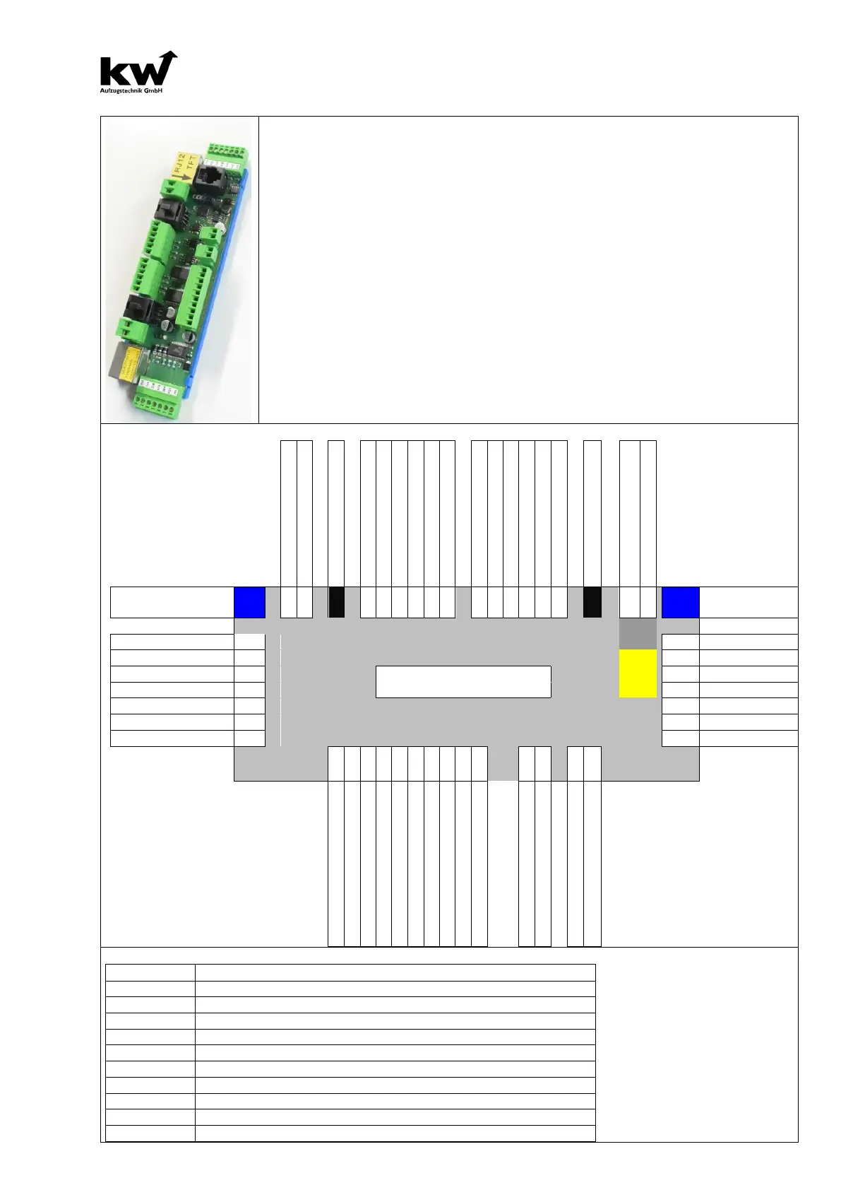
2.11 DESCRIPTION REMOTE STATION ER-2014
The remote station ER-2014 provides 16 inputs and outputs, including 6 free inputs
and outputs. There are 2 piece-outputs for the call messaging of bus-matrix-
The remote station has all necessary call-channels and arrow-outputs (even for se-
lective door-controlling). For
group are operating according 4 outputs for displaying
car position and 2 arrows per elevator. In addition, there are 2 Outputs for landing
operation and special trip per elevator. You connect 2 speak
for the gong of the floor.
You can modulate your gong signal at the options (volume, peach,
I which it sounds. (Car Call Up and Down, Landing Call Up and Down, Special trip…)
The lower 7-pin plug with the call-messaging 2xA & 2xB is responsible for the D
the upper plug with 2xC & 2xD for the Door 2.
The matrix-indicator with RJ-12 cable are to put in the 2 black jacks.
The yellow marked RJ-12 jack for high-quality TFT graphic displays with KW-bus con-
nection.
Bus- RJ-45 Blue
RJ45 Bus- RJ-
-12
or
Spezial Drive indicator A1, T1
Spezial Drive indicator A2, T2
Free: for example Landing Call Door 2 Up at selective Door
Free: for example Landing Call Door 2 Down at selective Door
Free: for example Level Arrow Door 1 Up
Free: for example Level Arrow Door 1 Down
Free: for example Level Arrow Door 2 Up
Free: for example Level Arrow Door 2 Down