KW Aufzugstechnik GmbH OPERATING MANUAL DAVID-613
DAVID-D613-V125-E 13.04.2021 Page - 125 -
B 46-R&S-Copy
1.0 General
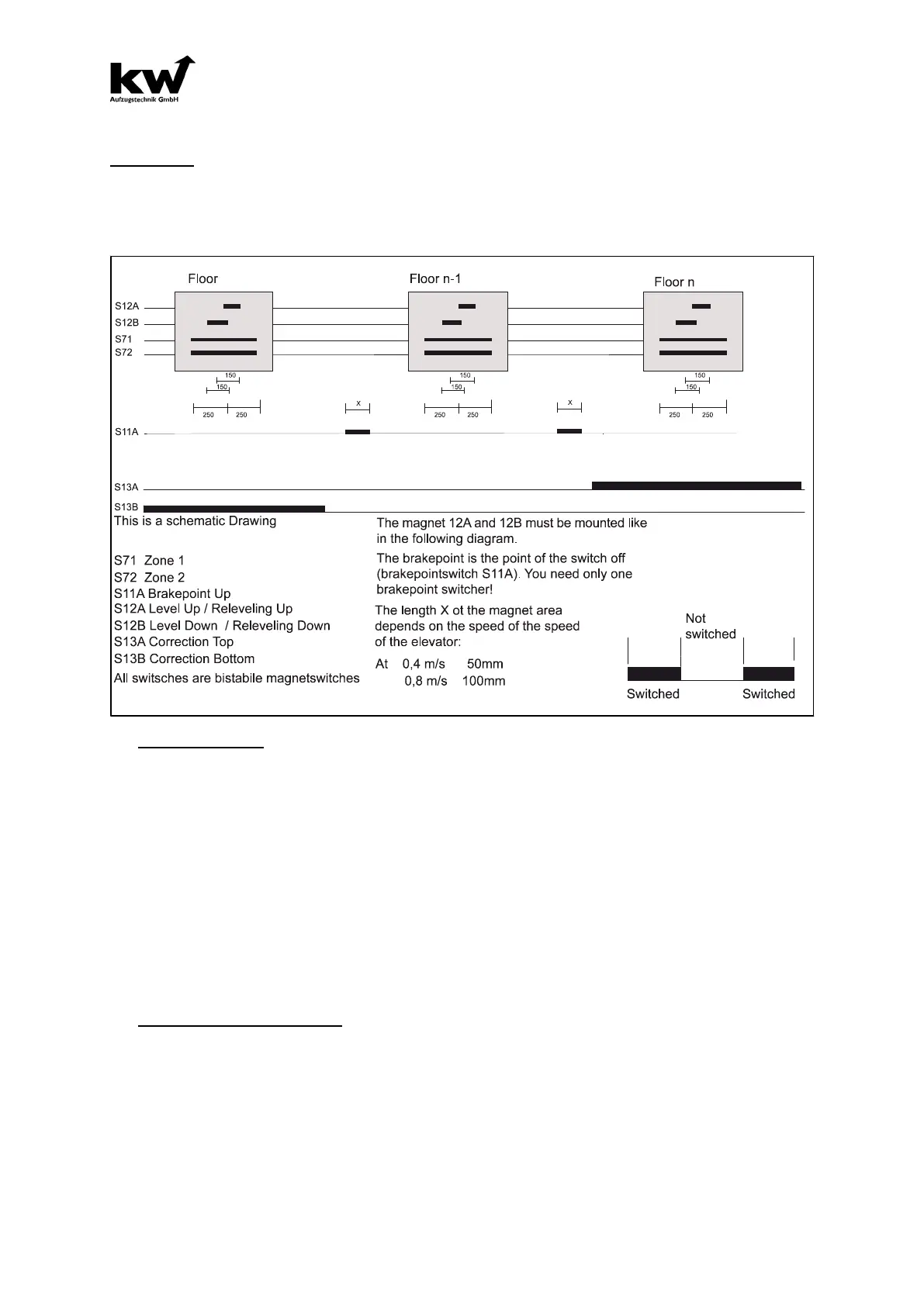
For R&S copying 5 magnet switchers are needed. If the elevator does not have a releveling function or
an entry with open doors the magnet counters S71 and S72 can be omitted. The precise position takes
place in regard to the direction. All magnet counters are instable block switches with the appropriate
round magnets. As an attachment for the magnets the guide rail as well as the shaft flag system can be
used ESK16.
4.0 Consice Position
The consice position is dependent on the direction.
The rope elevator system, when not entering an open door or readjusting the stop, is connected to
magnetic switch S12B in the upward direction and to magnetic switch S12A in the downward direction.
ATTENTION!
There may be a partial overlap of the consice magnet fields with precise position. From bottom
to top magnet 12B is always seen before 12A. The control recognizes the direction, however if
not executed correctly, floors will be counted falsely by the control.
On hydraulic lifts and cable systems with entrance, doors are opened or readjustment is maintained by
the stopping of the counter-aligned.
As long as both precise signals overlap themselves, no post-correction is necessary.
As soon as car sinks further or rises higher the precise signal is lost and so is the car after being ad-
justed into the opposite direction.
5.0 Brakepoints and Correction
The magnet switches 12A and 12B are also the brake-switches to drive to the destination floor. If you
are driving from the second floor to the first floor you do not need a brake magnet! You are braking with
the correction switch 13B. The same goes for ride from penultimate to the last stop (S13A). Switching
behavior of S11A is falling edge (turn-off). This way only one switch is necessary in shaft. The speed of
this method is a limit to the deceleration. Half of distance of the floor is the smallest stopping distance
possible.