3
K
B
K
I
H
K
K
K
K
K
J
3
G
K
L
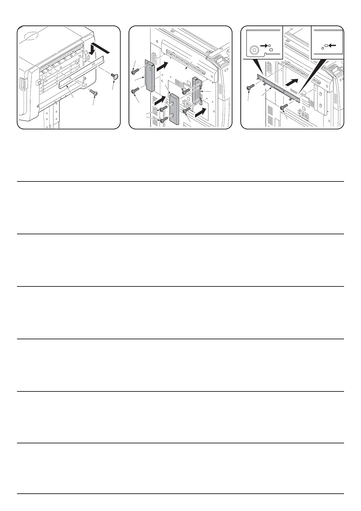
3. Secure the guide plate (G) using the
shoulder screw (L) and an S Tite screw M4 ×
10 (K).
4. Fit the fixing plate F (H) and the fixing plate
R (I) to the left cover (3) using two S Tite
screws M4 × 10 (K) for each and fit the cover
AT (J) to the fixing plate F (H) using two S
Tite screws M4 × 10 (K).
5. Fit the latch catch (B) to the fixing plate F (H)
and the fixing plate R (I) using two S Tite
screws M4 × 10 (K).
Attach with the upper screw holes
underneath fixing plates F (H) and R (I).
When using a full-color machine: Proceed to
step 7 on page 5
3. Fixez la plaque guide (G) à l’aide de la vis
d’épaule (L) et d’une vis S Tite M4 × 10 (K).
4. Fixer la plaque de fixation avant (H) et la
plaque de fixation arrière (I) sur le couvercle
de gauche (3) à l’aide de deux vis S Tite M4
× 10 (K) chaque et fixer le couvercle AT (J)
sur la plaque de fixation avant (H) à l’aide de
deux vis S Tite M4 × 10 (K).
5. Fixer le pontet du loquet (B) sur la plaque de
fixation avant (H) et sur la plaque de fixation
arrière (I) à l’aide de deux vis S Tite M4 × 10
(K).
Fixer à partir des trous de vis supérieurs se
trouvant sous les plaques de fixation avant (H)
et arrière (I).
Lors de l’utilisation de la machine entièrement
en couleurs: passer à l’étape 7 de la page 5
3. Asegure la placa guía (G) utilizando el
tornillo de hombro (L) y un tornillo S Tite M4
× 10 (K).
4. Encaje la placa de fijación F (H) y la placa de
fijación R (I) en la cubierta izquierda (3)
utilizando dos tornillos S Tite M4 × 10 (K)
para cada una y encaje la cubierta AT (J) en
la placa de fijación F (H) utilizando dos
tornillos S Tite M4 × 10 (K).
5. Encaje el cerrojo (B) en la placa de fijación F
(H) y la placa de fijación R (I) utilizando los
dos tornillos S Tite M4 × 10 (K).
Fije con los orificios para tornillos superiores
debajo de las placas de fijación F (H) y R (I).
Cuando utilice una máquina a todo color:
Vaya al paso 7 de la página 5
3. Die Führungsplatte (G) mit der
Bundschraube (L) und einer S-Tite-
Schraube M4 × 10 (K) befestigen.
4. Die Fixierplatte F (H) und die Fixierplatte R
(I) mit je zwei S-Tite-Schrauben M4 × 10 (K)
an der linken Abdeckung (3) anbringen, und
die Abdeckung AT (J) mit zwei S-Tite-
Schrauben M4 × 10 (K) an der Fixierplatte F
(H) anbringen.
5. Die Riegelschloßbausatz (B) mit zwei S-Tite-
Schrauben M4 × 10 (K) an der Fixierplatte F
(H) und die Fixierplatte R (I) anbringen.
Mit den oberen Schraublöchern unter den
Fixierplatten F (H) und R (I) anbringen.
Bei Verwendung eines Vollfarbenkopierers:
Gehen Sie zum Schritt 7 auf Seite 5 weiter
3. Fissare la piastra della guida (G) utilizzando
la vite a colletto (L) e la vite S Tite M4 × 10
(K).
4. Montare la piastra di fissaggio F (H) e la
piastra di fissaggio R (I) sul coperchio
sinistro (3) usando due vite S Tite M4 × 10
(K) per ciascuna di esse e montare il
coperchio AT (J) sulla piastra di fissaggio F
(H) usando due vite S Tite M4 × 10 (K).
5. Montare il dispositivo di arresto (B) sulla
piastra di fissaggio F (H) e sulla piastra di
fissaggio R (I) usando due vite S Tite M4 ×
10 (K).
Collegare con i fori per le viti superiori, sotto
le piastre di fissaggio F (H) e R (I).
IN caso si utilizzi un macchinario a colori:
Procedere con il punto 7 a pagina 5
3. ガイド板 (G) を段付きビス (L) とビス M4 ×
10S タイト (K) 各1本で固定する。
4. 固定板 F(H) と固定板 R(I) を左カバー(3)
にビス M4 × 10S タイト (K) 各 2 本で固定
し、カバーAT(J) をビス M4 × 10S タイト
(K)2 本で固定板 F(H) に固定する。
5. ラッチ受け板 (B) をビス M4 × 10S タイト
(K)2 本で固定板 F(H) と固定板 R(I) に固定
する。
固定板 F(H) と固定板 R(I) の上側のビス穴
で固定すること。
フルカラー機の場合:5 ページ手順 7 へ進む。
3. 在用阶梯螺钉 (L) 和紧固螺钉 M4 × 10S (K) 各
1 个固定导板 (G)。
4. 将固定板 F (H) 和固定板 R (I) 分别用 2 个紧固
螺丝 M4 × 10S (K) 固定在左盖板 (3) 上,将盖
板 AT (J) 用 2 个紧固螺丝 M4 × 10S (K) 固定在
固定板 F (H) 上。
5. 挂钩承支架 (B) 用 2 个紧固螺丝 M4 × 10S (K)
固定在固定板 F (H) 和固定板 R (I) 上。
把固定板 F(H)和 R(I)固定在上侧的螺丝孔
处。
使用全彩色机时:进行第 5 页上的第 7 步
 Loading...