2NL/2P8
1-2-21
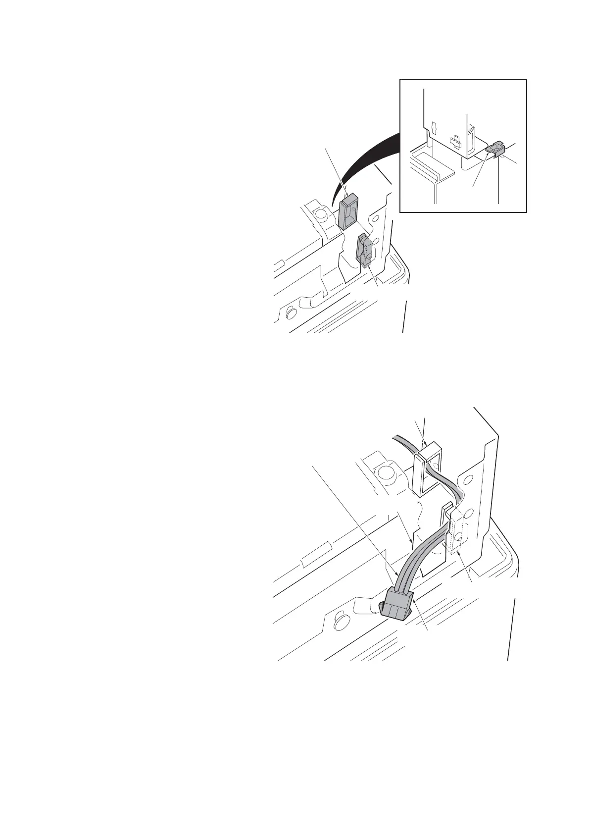
12. Attaches the wire saddle B and the wire
saddle C to right upper section of the
machine and then release two hooks of
the thir.
13. Attach the edging to the aperture part.
Figure 1-2-24
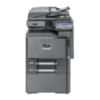
14. Pass the key counter electrical wires
through the wire saddle B and the wire
saddle C and then pull out from the
aperture part.
Figure 1-2-25
Wire saddle B
Wire saddle C
Edging
Connector
Wire saddle B
Wire saddle C
Aperture
Key counter
electrical wires





 To Next Page