2NL/2P8
1-2-56
1-2-8 Installing the Printed Document Guard Kit (option)
Printed Document Guard Kit installation requires the following parts:
Supplied parts of Printed Document Guard Kit :
* : Not used in this model.
▲: One piece is used in this model.
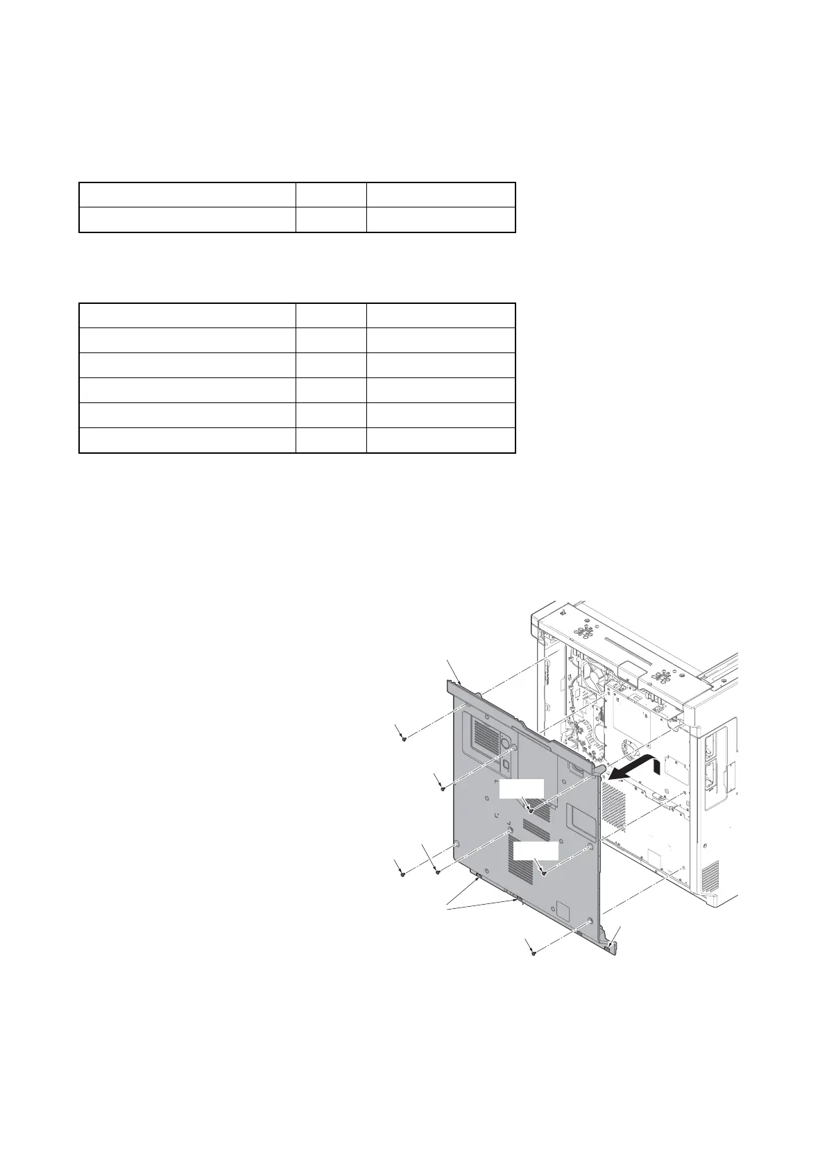
Procedure
1. Press the power key on the operation
panel to off. Make sure that the power
indicator and the memory indicator are
off before turning off the main power
switch. And then unplug the power
cable from the wall outlet.
2. Remove seven screws.
3. Pull the rear cover upwards and then
release three hooks.
4. Remove the rear cover.
5. When not using DP junction PWB, the
following procedures 6 to 11 are fol-
lowed, and when using it, Procedure 13
to 20 is performed.
Figure 1-2-77
Parts Quantity Part.No.
Printed Document Guard Kit (B) 1 1503P40UN0
Parts Quantity Part.No.
Copy guard PWB 1 -
FFC (short) 2* -
FFC (long) 2 -
Mount plate B 1* -
Screw M3 x 6 2▲ -
Screw
Screw
Screw
Screw
Rear cover
Hooks
Hook
Screw
Screw
Screw