2NL/2P8
1-2-22
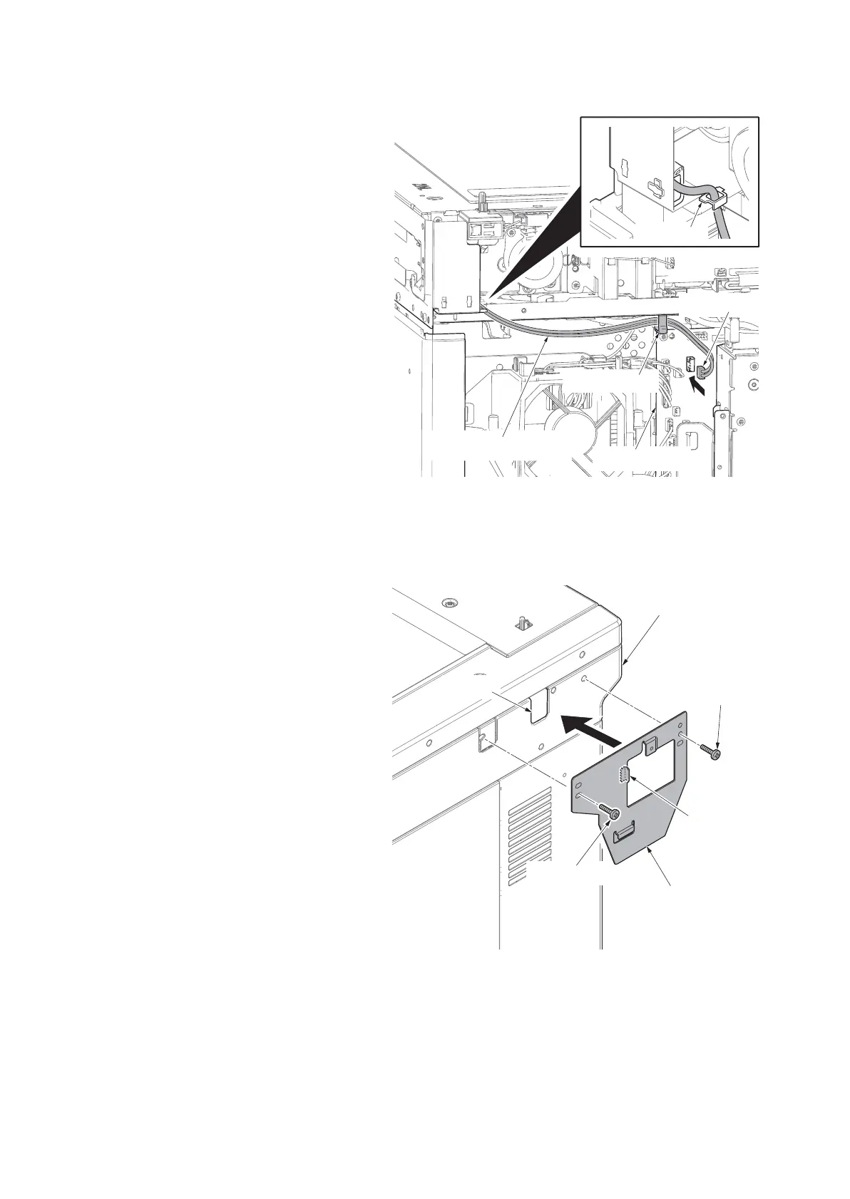
15. Pass the key counter wires through the
edging.
16. Pass the key counter wires through the
wire saddle and then connect the
connector of the key counter wires to
the connector of the engine PWB.
17. Fit the scanner rear cover using two
screws.
18. Fit the right upper cover.
Note: Pass the connector of the key
counter wire through the aperture (right
side) in the right upper cover.
Note: Be careful not to put a key coun-
ter electric wire with the upper right
cover.
19. Fit the scanner right cover using two
screws.
Figure 1-2-26
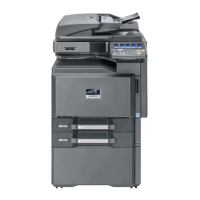
20. Insert the projection of the key counter
cover retainer in the aperture of the
right upper cover.
21. Fit the key counter cover retainer using
the two M4 x 10 screws.
Figure 1-2-27
Engine PWB
Key counter wires
Wire saddle
Edgeing
Connector
Right upper cover
Aperture
Key counter
cover retainer
M4x10 screw
M4x10 screw
Projection





 To Next Page