LACO ORIGINAL OPERATING INSTRUCTIONS TITANTEST™
35
© 2018 LACO TECHNOLOGIES, INC. - [TitanTest itna01en1-07 BA.fm] - 1807
Analog output
► Select " Setup > Global settings > Interfaces > Analog Output".
Control location** Define the control location from which the T
ITANTEST™ is controlled.
► Select " Setup > Global settings > Interfaces > Control Location".
** Feature not available in TITANTEST™ Maintenance model
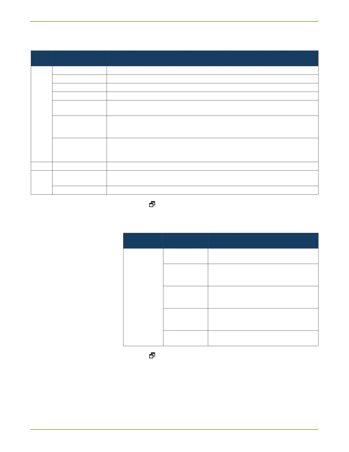
Table 13: Analog output settings
Option Value range
(Min. Max.)
Comment
Channel 1 OFF Channel 1 is switched off (0 V).
Pressure p2 The inlet pressure p2 is output to Channel 1.
Pressure p1 The fore-vacuum pressure p1 is output to Channel 1 ).
LR mantissa The leakage rate mantissa is output linearly from 1...10 V (e.g. 5.4 x 10
-7
mbar l/s corresponds to 5.4V).
LR exponent The exponent is output as a step function: U = 1…10 V in steps from 0.5 V per decade beginning at
1 V = 1x10
-12
(e.g. 5.4 x 10
-7
mbar l/s corresponds to 3.5 V).
LR linear The leakage rate mantissa is linearly output from 1 ... 10V. The upper limit (=10 V) is specified via the setting
"Scaling
upper limit" (see below).
For example: 5.4 x 10
-7
mbar l/s and upper limit 1 x 10
-6
mbar l/s corresponds to 5.4V.
LR log. The output voltages are scaled logarithmically. The upper limit (=10 V) is specified via the setting "Scaling
upper limit". The increase is specified via "Scaling V/Decade".
For example: 10
-7
mbar l/s, upper limit 10
-6
mbar l/s and 2V/decade corresponds to an output voltage of 8V.
Channel 2 see Channel 1 analog to Channel 1
Scaling upper limit
1E-11 … 1E+6
upper limit (=10 V) for setting "LR log." and "LR linear".
V/Decade: 0.5, 1, 2, 2.5, 5, 10 Volt per decade for setting "LR log."
Table 14: Control location settings
Option Value range
(Min. Max.)
Comment
Control location** Local The T
ITANTEST™ is controlled with the buttons START, STOP and
ZERO.
Local and RS232 /
RS485
The T
ITANTEST™ is controlled both with the START / STOP and
ZERO buttons on the device and via the RS232 / RS485 inter-
face.
RS232 / RS485 The T
ITANTEST™ is controlled by an external computer via the
RS232 / RS485 interface. The START / STOP and ZERO buttons
on the device are deactivated.
All The T
ITANTEST™ is controlled both with the START/STOP and
ZERO buttons on the device and via the digital inputs and
RS232/RS485 interface.
PLC The T
ITANTEST™ is controlled via the digital input. The START/
STOP and ZERO buttons on the device are deactivated.