PLMNL0232 REV. H Effective Date: 01/14/19 43 FiberCUT
®
2D Operation Manual
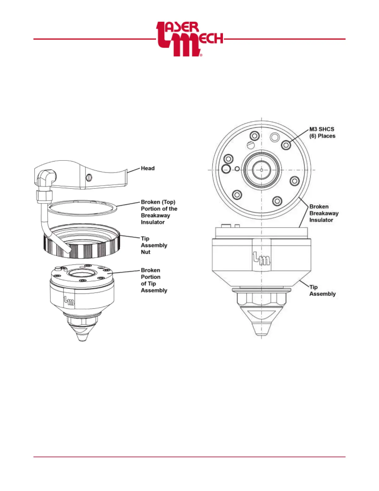
1. Gather the tip assembly if it was
fractured from the head.
For steps 2 and 3, see Figure 57.
2. Unscrew the tip assembly nut from the
head.
3. If it was fractured, remove the broken
(top) portion of the breakaway insulator
from inside the tip assembly nut.
Figure 57
4. Remove the (6) M3 SHCS that secure
the broken breakaway insulator to the
tip assembly. See Figure 58.
5. Remove the breakaway insulator with
the o-rings. See Figure 59.
Figure 58
To install a breakaway insulator:
For steps 6 to 9, see Figure 59.
6. Verify that all (4) o-rings are present
and installed correctly:
In both the breakaway insert and the
tip assembly:
o (1) smaller o-ring near the edge
o (1) larger o-ring at the center