Table 37: Cooling circulation thermostats and heating circulation thermostats
Unit RP 240 E RP 245 E RP 250 E RP 290 E P 2 E
*ACC area/working tem-
perature range
°C -40 – 200* -45 – 200* -50 – 200* -90 – 200* 80 – 250
Operating temperature
range (heating device with
external cooling)
°C --- --- --- --- -30 – 250
Device dimensions (W x D) mm 300 x 430 300 x 430 300 x 430 390 x 600 250 x 365
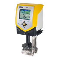
Device height (H), including
Command Touch unit
mm 675 675 675 685 425
Filling volume
‑ maximum L 4.4 4.4 4.4 4.4 4.4
‑ minimum L 2.4 2.4 2.4 2.4 2.4
Pump data
Maximum discharge pres-
sure
bar 0.7 0.7 0.7 0.7 0.7
Maximum pump suction bar 0.4 0.4 0.4 0.4 0.4
Maximum flow rate pressure l/min 22 22 22 22 22
Maximum flow rate suction l/min 20 20 20 20 20
Pump connecting thread mm M16 x 1 M16 x 1 M16 x 1 M16 x 1 M16 x 1
Connecting thread on
cooling coil (thermal devices
only)
Inches --- --- --- ---
Thread G3/8"
external &
G1/4" internal
Noise level (1 m) dB(A) 54 54 57 56 47
Weight kg 46 46 47 79 16
Clearance
‑ Front mm 200 200 200 200 200
‑ Back mm 200 200 200 200 200
‑ Right mm 200 200 200 200 200
‑ Left mm 200 200 200 200 200
*ACC area (Active Cooling Control) according to DIN 12876 is
the working temperature range during operation with an active
refrigerating machine.
11.2 Cooling capacity and cooling water
The devices are operated with partially halogenated and/or natural
refrigerant, depending on the device model. The cooling output
values measured for partially halogenated refrigerant and natural
refrigerant are identical. The designation and refrigerant charge are
specified on the device type plate.
V6 PRO bath thermostats and circulation thermostats 133 / 156