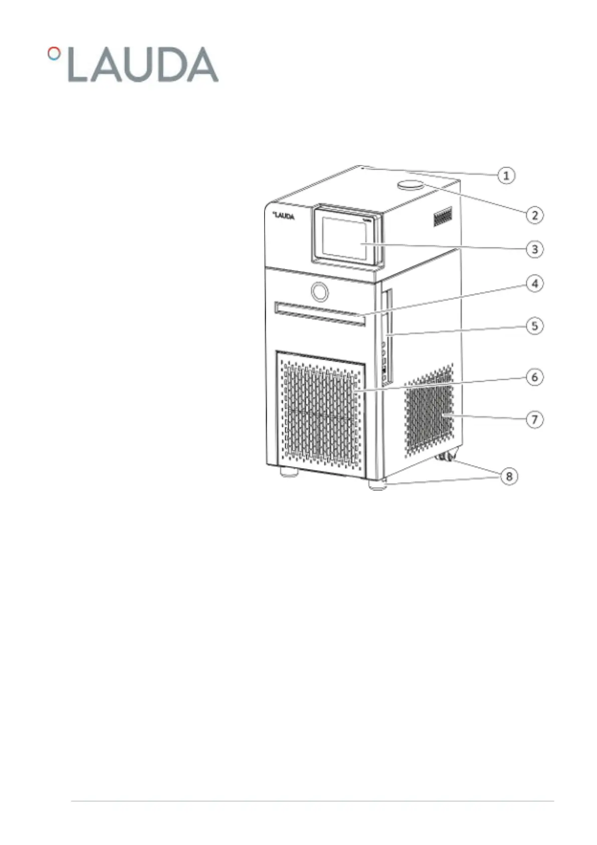
3.1.2 Structure of the circulation thermostats
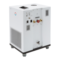
Fig. 3: Circulating thermostat with refrigerating machine, front view
1 Visual operation and fault indicator (LED)
2 Tank filler neck
3 Command Touch remote control unit
4 Recessed grip
5 Interfaces
6 Front panel (detachable)
7 Ventilation grid
8 Feet at front; castors at rear
Front
V6 PRO bath thermostats and circulation thermostats 19 / 156