LAUNCH X-431 PAD III User Manual
100
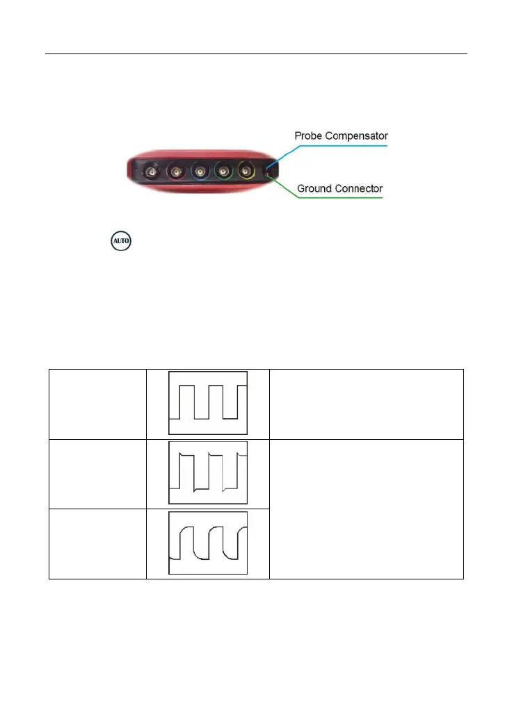
reference lead to the ground connector. When using the probe hook-tip,
insert the tip onto the probe compensator firmly to ensure a proper
connection.
Fig 12-2
5. Tap the button located on the bottom of the screen, a square wave
(approximately 1kHzm 2V peak-to-peak) will be displayed within several
seconds.
*Note: The above steps also can be applied to check whether the signal
input/output of other Channels are normal or not.
Check the shape of the displayed waveform to determine whether the probe
is correctly compensated.
Correctly
Compensated
Over
Compensated
*Note: If necessary, use a
non-metallic tool to adjust the
trimmer capacitor of the probe for
the fattest square wave being
displayed on the Scopebox.
Under
Compensated
*Warning: To avoid electric shock while using the probe, make sure the insulated cable
is perfect, and do not touch the metallic portions of the probe head while it is
connected with a high-voltage source.
 Loading...