LAUNCH X-431 PAD III User Manual
101
12.3.2 Connection
For different applications, the connection methods may vary.
1. Power the Scopebox on: Power is provided to the Scopebox in either of the
following ways:
• Power adaptor: Insert one end of the power adaptor into the Power
interface of the Scopebox, and the other end to the AC outlet.
• Battery clamps cable: Plug one end of the power adaptor into the Power
interface of the Scopebox, and then clamp the other two terminals to the
vehicle's battery (Red to +, and Black to -) respectively.
2. Connect the B-shaped terminal of the USB cable to the Scopebox USB port,
and the other end to the USB port of the diagnostic tool.
A. While testing sensors or actuators,
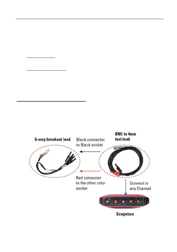
3. Connect the BNC connector of the BNC to 4mm test lead to the
CH1/CH2/CH3/CH4, and plug the black (GND) and red (SIGNAL) 4mm
connectors into the Black (GND) and other color (SIGNAL) banana sockets of
the 6-way breakout leads respectively.
Fig. 12-3
4. Connect the black terminal and signal wire (its other end connected to the red
4mm connector) of the 6-way breakout lead to the GND and signal terminal of