LAUNCH X-431 PAD III User Manual
24
launched, you can also configure it while using the software.
To obtain stable communication, you are strongly recommended to perform the
vehicle diagnosis via USB cable. In this case, the USB cable is required to connect
the VCI module and the X-431 PAD III tablet.
To ensure that the X-431 PAD III tablet can work with the VCI module via Wi-Fi
communication, a Wi-Fi configuration is required. Refer to Chapter 4.5.3 for details.
When all communication methods are applied at the same time, the X-431 PAD III
system will use the USB communication as the default priority.
4.4 Connections
4.4.1 Preparation
Normal testing conditions
Turn on the vehicle power supply.
Throttle should be in a closed position.
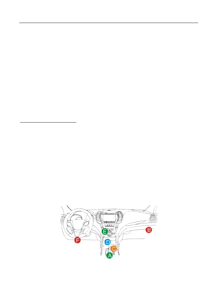
4.4.2 DLC location
The DLC (Data Link Connector) is typically a standard 16 pin connector where
diagnostic code readers interface with the vehicle’s on-board computer. The
DLC is usually located 12 inches from the center of the instrument panel (dash),
under or around the driver’s side for most vehicles. If Data Link Connector is not
located under dashboard, a label should be there telling location. For some
Asian and European vehicles, the DLC is located behind the ashtray and the
ashtray must be removed to access the connector. If the DLC cannot be found,
refer to the vehicle’s service manual for the location.
Fig. 4-11
4.4.3 Vehicle connection (For Passenger Vehicle Version)
The method used to connect the diagnostic connector to a vehicle’s DLC