LAUNCH X-431 PAD III User Manual
77
probe is the output terminal of simulation voltage.
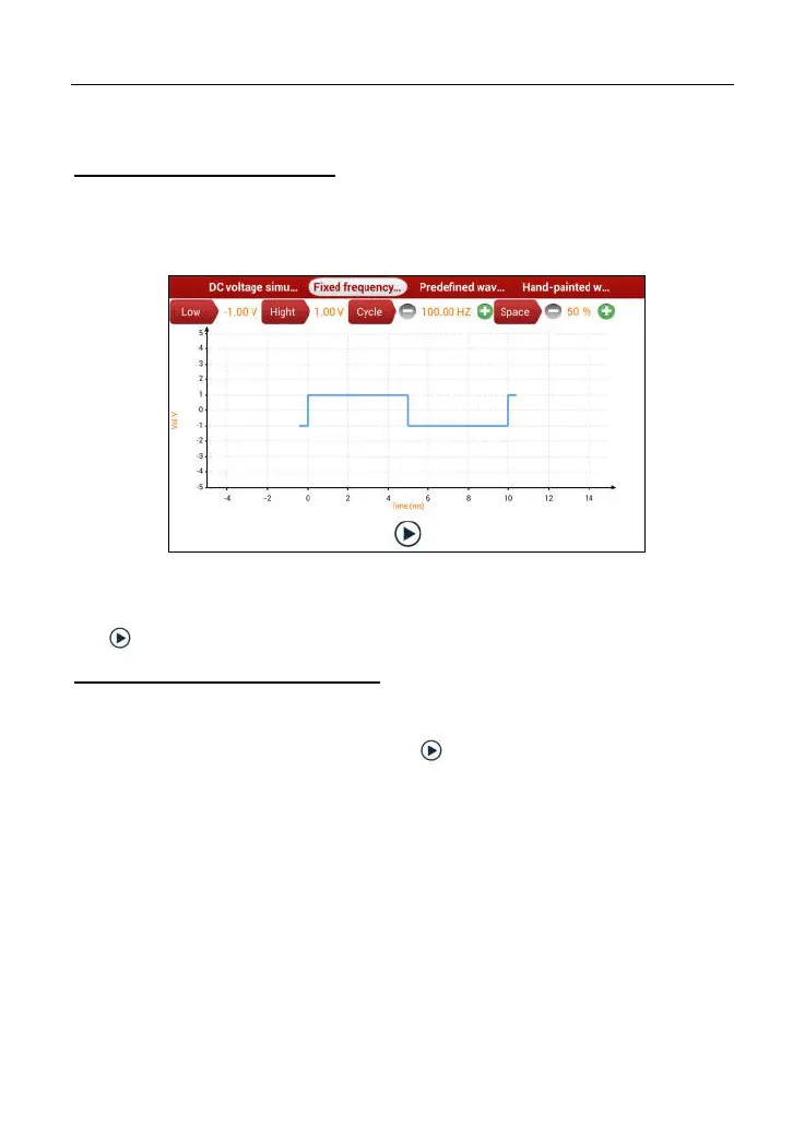
2. Fixed frequency simulation
This option enables you to simulate the square wave signal of pulse frequency
of 0.1 ~ 15 kHz, amplitude range of -5V ~ +5V and duty cycle 10% ~ 90%.
In Fig. 9-2, tap “Fixed frequency simulation” to enter a screen similar to Fig. 9-3.
Fig. 9-3
Tap the setting option tab, then tap “+” or “-” to adjust the output. After setting,
tap to perform the test.
3. Predefined waveform simulation
X-431 PAD III provides some common sensor waveforms which have been
predefined to facilitate users to simulate sensor signals. As long as you call out
the predefined waveform, then tap to start simulating output of
corresponding sensor waveform and no more parameter settings of simulation
waveform are required.
In Fig. 9-3, tap “Predefined waveform simulation” to enter the screen shown as
Fig. 9-4.