31
UserManualforELD2Servo
2. When you compose a position loop outside of the driver while you use the driver in velocity
control mode, the setup of Pr3.02 gives larger variance to the overall servo system.
3. Pay an extra attention to oscillation caused by larger setup of Pr3.02.
Pr3.03
Reversalofspeedcommandinput
Range unit default
Related
control mode
0‐1
‐
500 S
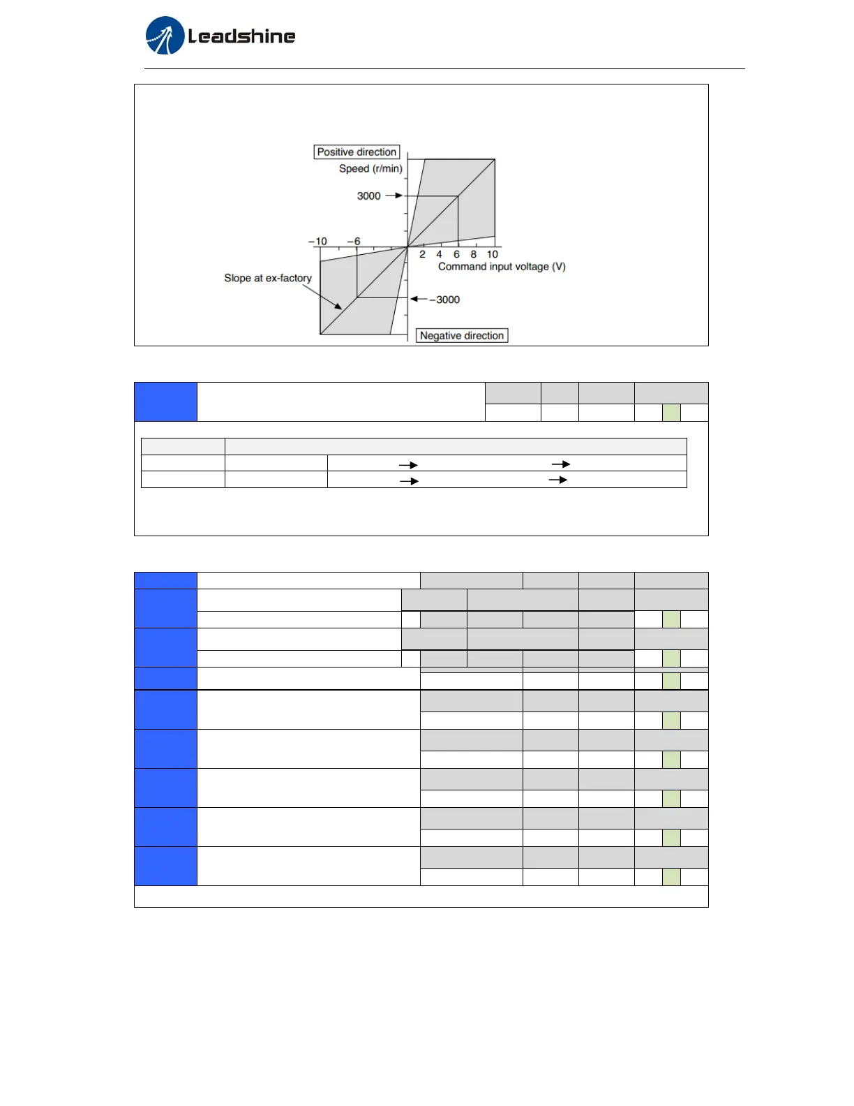
Specify the polarity of the voltage applied to the analog speed command (SPR).
Setup value Motor rotating direction
0 Non-reversal [+ voltage] [+ direction] [- voltage] [-direction]
1 reversal [+ voltage] [- direction] [- voltage] [+direction]
Caution: When you compose the servo drive system with this driver set to velocity control mode and
external positioning unit, the motor might perform an abnormal action if the polarity of the speed
command signal from the unit and the polarity of this parameter setup does not match.
Pr3.04
1stspeedofspeedsetup
Range unit default
Related
control mode
‐20000‐20000
r/min
0 S
Pr3.05
2ndspeedofspeedsetup
Range unit default
Related
control mode
‐20000‐20000
r/min
0 S
Pr3.06
3rdspeedofspeedsetup
Range unit default
Related
control mode
‐20000‐20000
r/min
0 S
Pr3.07
4thspeedofspeedsetup
Range unit default
Related
control mode
‐20000‐20000
r/min
0 S
Pr3.08
5thspeedofspeedsetup
Range unit default
Related
control mode
‐20000‐20000
r/min
0 S
Pr3.09
6thspeedofspeedsetup
Range unit default
Related
control mode
‐20000‐20000
r/min
0 S
Pr3.10
7thspeedofspeedsetup
Range unit default
Related
control mode
‐20000‐20000
r/min
0 S
Pr3.11
8thspeedofspeedsetup
Range unit default
Related
control mode
‐20000‐20000
r/min
0 S
Set up internal command speeds, 1st to 8th
Pr3.12
timesetupacceleration
Range unit default
Related
control mode
0‐10000
Ms(1000r/min)
100 S
Pr3.13
timesetupdeceleration
Range unit default
Related
control mode
0‐10000
Ms(1000r/min)
100 S
Set up acceleration/decelerationprocessingtimeinresponsetothespeedcommandinput.