X75HD Installation and Operation Manual 39
Chapter 3: Module and Back Panel Descriptions
Preliminary—Contents are proprietary and confidential. Do not photocopy or distribute.
Required Jumper Settings and Local Configuration
Setting Jumpers
The AS-X75HD module requires you to configure several jumpers
prior to operation to properly configure both the analog audio input and
output impedance.
• Set jumpers J5 through J8 to configure the analog audio input
impedance. To do this, place a jumper on pins 1 and 2 to set the
input impedance to 600W, or on pins 2 and 3 to set the input
impedance to 100 kW. Make the same impedance setting to all
required jumpers (J5, J6, J7, J8).
• Set jumpers J1 through J4, and J9 through J12 to configure the
analog audio output impedance. To do this, place a jumper on pins 1
and 2 to set the output impedance to 600W, or on pins 2 and 3 to set
the output impedance to 66W. Make the same impedance setting to
all required jumpers (J1, J2, J3, J4, J9, J10, J11, J12).
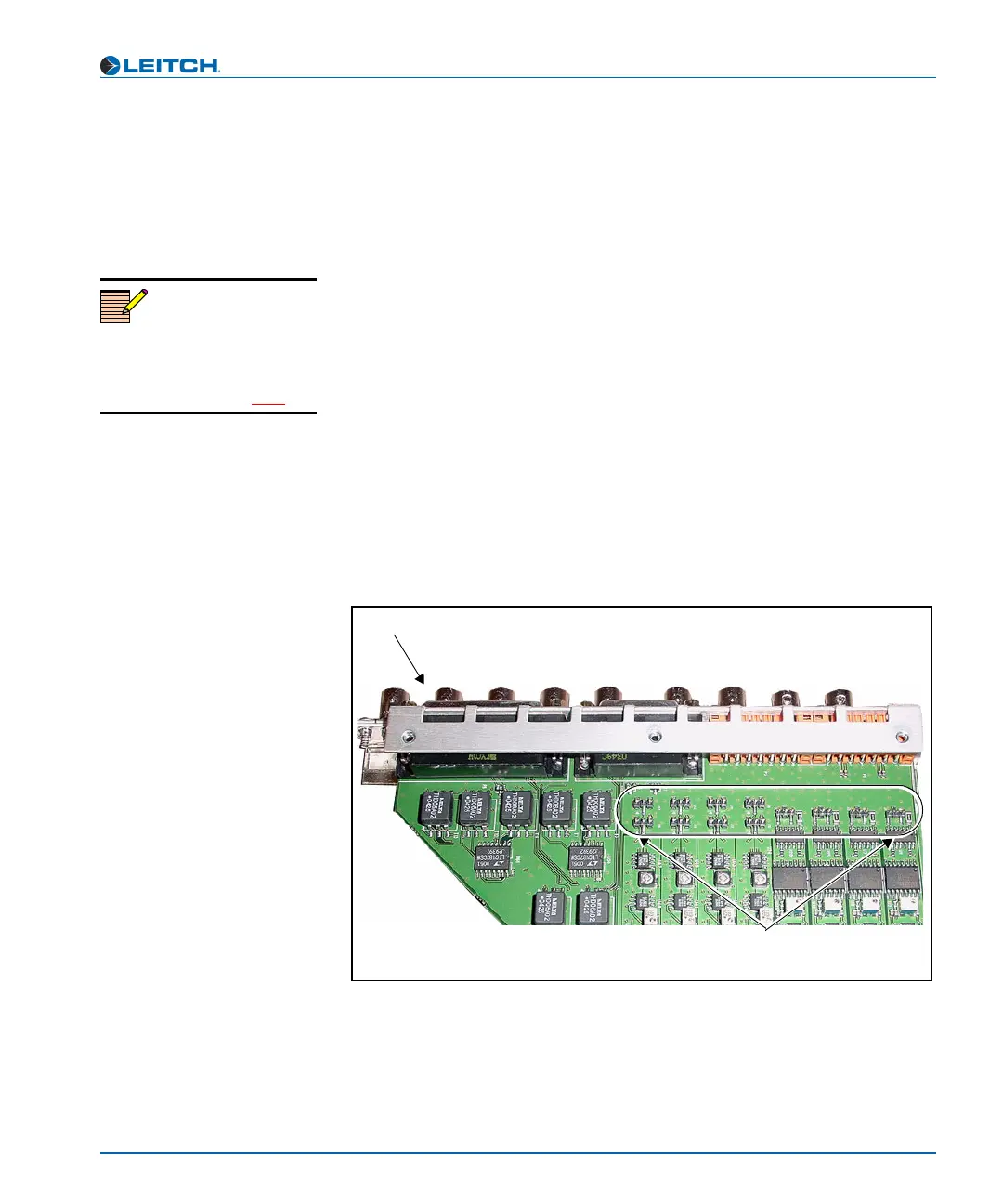
Jumpers 1 through 12 can all be found at the rear of the board, located
directly behind the back panel. Figure 3-2 shows their general location.
Figure 3-2. AS-X75HD Jumper Locations
Note
Beside each jumper described in
this section, there is a white
triangle screened on the board.
This triangle points to pin 1.
Back panel connectors
Jumpers J1
through J12