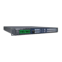
60 X75HD Installation and Operation Manual
Preliminary—Contents are proprietary and confidential. Do not photocopy or distribute.
Chapter 4: System Installation and Connections
HDTV Serial Digital Inputs
There are three HDTV video input connectors on the X75HD frame that
allow for three possible input choices. Choose from HD-FIBER,
HD1 IN, or HD2 IN.
HDTV Serial Digital Outputs
There are three available outputs on the X75HD frame: HD-FIBER,
HD1 OUT, and HD2 OUT. All three outputs will contain the same
content.
Genlock Input
This BNC connector, labeled GENLOCK, is used to input a genlock
signal to establish the timing for the video output signal. The signal for
this input must always be stable, such as the output from a black-burst
or color-bar generator. Do not attempt to use a signal that has not been
time base-corrected.
The you can choose one of the following reference locking sources:
• External reference input, either color black or tri-level sync
• Internal clock generated by the X75HD
• Any video input, including HD fiber, HD1, HD2, SDI1, SDI2, DV,
composite, analog component, s-video
When a valid signal is connected to the genlock input, all video outputs
from the X75HD will be genlocked to this signal, and the Genlock LED
will be on. When no external reference is supplied to the genlock input,
the unit will operate using its own internal clock.
Component Analog Video Outputs
These three BNC connectors, labeled CAV-Y OUT, R-Y OUT, and B-Y
OUT, are used to output the signals to analog component devices, such
as Betacam VTRs.
Composite Video Output
This BNC connector, labeled Composite Out, provides processed,
synchronized versions of any of the input signals.