© Copyright Lenovo 2017 Chapter 10: Spanning Tree Protocols 189
MSTP Configuration Example 2
ThisconfigurationshowshowtoconfigureMSTPGroupsontheswitch,asshown
inFigure 15.
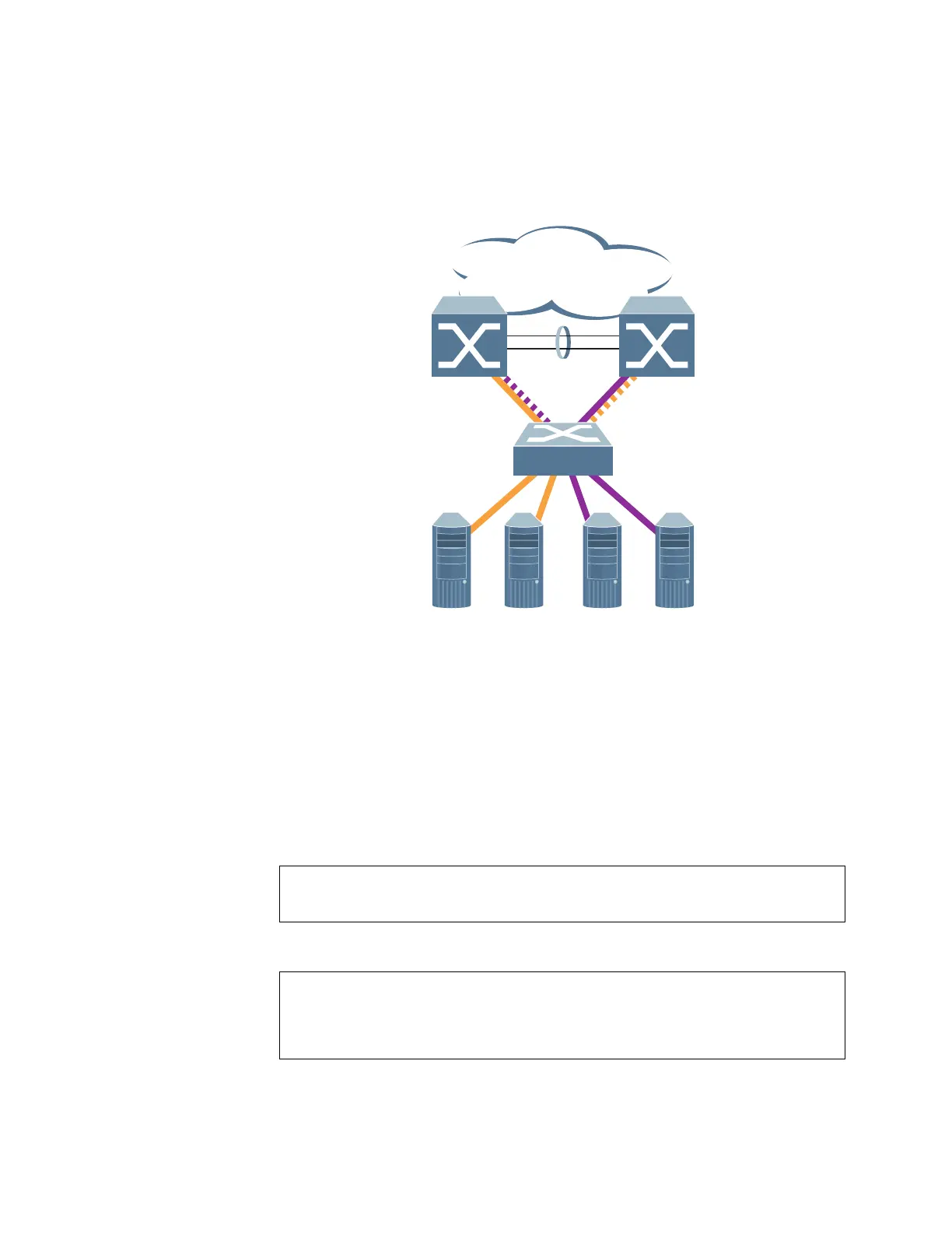
Figure 15. ImplementingMultipleSpanningTreeGroups
ThisexampleshowshowmultipleSpanningTreescanprovideredundancy
withoutwastinganyuplinkports.Inthisexample,theserverportsaresplit
betweentwoseparateVLANs.BothVLANsbelong
totwodifferentMSTPgroups.
TheSpanningTreepriorityvaluesareconfiguredsothateachroutingswitchisthe
rootforadifferentMSTPinstance.Alloftheuplinksareactive,witheachuplink
portbackinguptheother.
1. ConfigureportmembershipanddefinetheSTGsforVLAN1.Enable
taggingon
uplinkportsthatshareVLANs.Port19andport20connecttotheEnterprise
Routingswitches.
2. ConfigureMSTP:SpanningTreemode,regionname,andversion.
Enterprise
Routing Switch
MSTP Group 1
Root
Enterprise
Routing Switch
MSTP Group 2
Root
Server 1
VLAN 1
Server 2
VLAN 1
Server 3
VLAN 2
Server 4
VLAN 2
Blocking VLAN 1
Passing VLAN 2
Passing VLAN 1
Blocking VLAN 2
CN 4093(config)# interface port 19,20
CN 4093(config-if)# switchport mode trunk
CN 4093(config-if)# exit
CN 4093(config)# spanning-tree mst configuration
CN 4093(config-mst)# name MyRegion (DefinetheRegionname)
CN 4093(config-mst)# revision 100 (DefinetheRevisionlevel)
CN 4093(config-mst)# exit
CN 4093(config)# spanning-tree mode mst(SetmodetoMultipleSpanningTrees)

 Loading...