© Copyright Lenovo 2017 Chapter 34: Virtual Router Redundancy Protocol 535
Hot-Standby Configuration
TheprimaryapplicationforVRRP‐basedhot‐standbyistosupportNetwork
AdapterTeamingonyourserverblades.WithNetworkAdapterTeaming,the
NICsoneachserversharethesameIPv4address,andareconfiguredintoateam.
OneNICistheprimarylink,andtheothersarebackuplinks.For
moredetails,
refertotheNetXen10GbEthernetAdapterdocumentation.
Ahot‐standbyconfigurationallowsallprocessestofailovertoastandbyswitchif
anytypeoffailureshouldoccur.AllVirtualInterfaceRouters (VIRs)arebundled
intooneVirtualRoutergroup,andthentheyfailovertogether.Whenthereis
a
failurethatcausestheVRRPMastertofailovertotheStandby,thenthe original
primaryswitchtemporarilydisablestheinternalserverlinks,which,inturn,
causestheNICteamstofailoveraswell.
Note: Whenusinghot‐standbyredundancy,peerswitchesshouldhaveanequal
numberofconnectedports.
Ifhot
‐standbyisimplementedinaloopedenvironment,thehot‐standbyfeature
automaticallydisablesthehot‐standbyportsontheVRR PStandby.IftheMaster
switchshouldfailovertotheStandbyswitch,itwouldchangethehot‐standby
portsfromdisabledtoforwarding,withoutrelyingonSpanningTreeormanual
intervention.
Therefore,SpanningTreemustbedisabled.
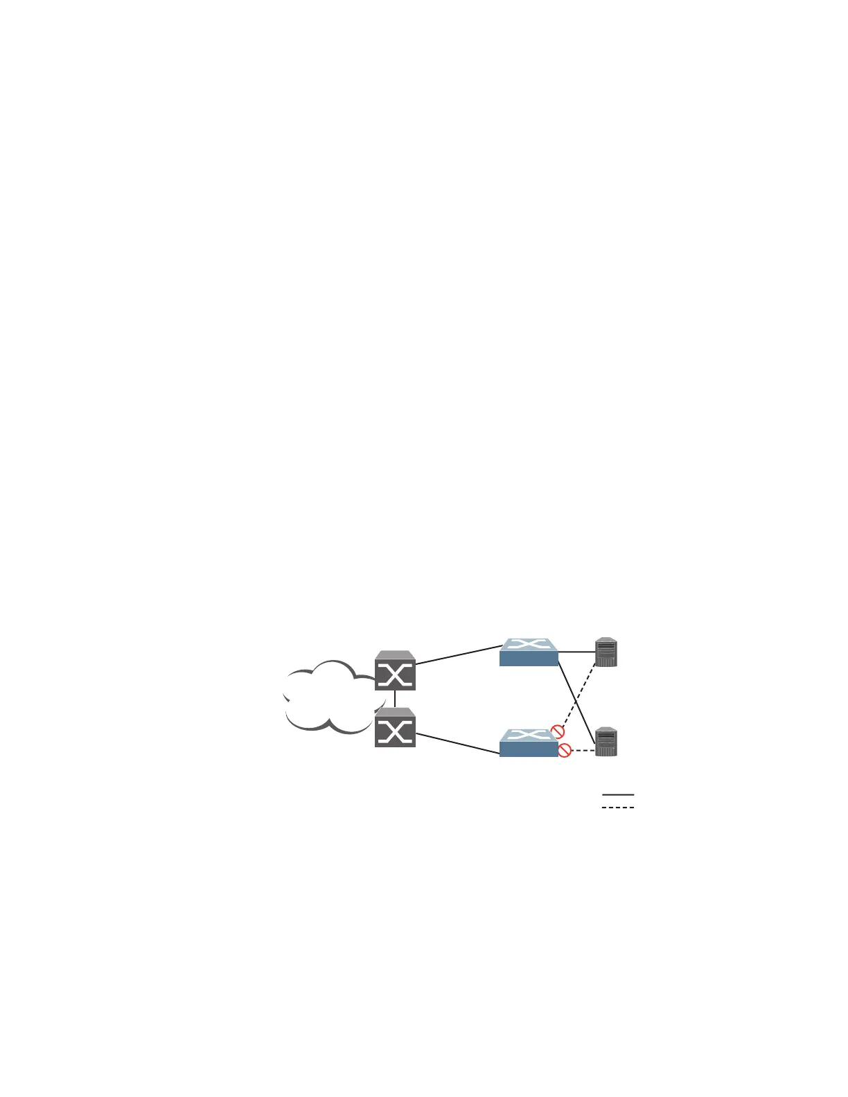
Figure 64illustratesacommonhot‐standbyimplementationonasingleblade
server.NoticethatthebladeserverNICsareconfiguredintoateamthatsharesthe
sameIPv4addressacrossbothNICs.Becauseonlyonelinkcanbeactiveatatime,
thehot‐standby
featurecontrolstheNICfailoverbyhavingtheStandbyswitch
disableitsinternalports(holdingdowntheserverlinks).
Figure 64. Hot‐StandbyConfiguration
Enterprise
Routing Switch
Server 2
Active
Switch 1
Hot Standby
Switch 2
NIC 1 IP = 10.0.1.1
Server 1
NIC 1 IP = 10.0.1.2
IF 1: 174.14.20.110
IF 2: 10.1.1.110
VIR 1: 174.14.20.100
VIR 2: 10.1.1.100
IF 1: 174.14.20.111
IF 2: 10.1.1.111
VIR 1: 174.14.20.100
VIR 2: 10.1.1.100
= Active Links
= Standby Links
Internet

 Loading...