Parameter setting with the XT EMZ9371BC keypad
Menu structure
9
Parameter setting
9.4
9.4.8
L
9.4-14
EDS82EV903-1.0-11/2002
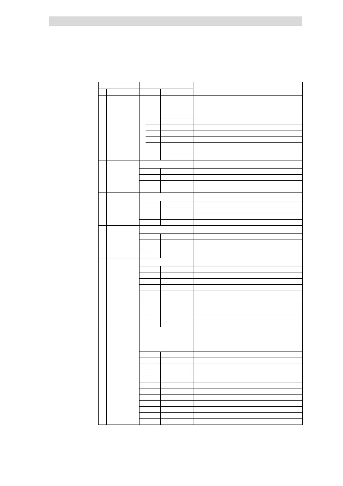
Main menu DescriptionSubmenus
No.
Description
DisplayNo.Display
5.27 PID-Ctrl 7 Operation with fieldbus function module on FIF (DRIVECOM
control)
Frequency setpoint via process data channel
Actual frequency via process data channel
5.27.1 FIF managem Set up fieldbus communication
5.27.2 Setpoint Setpoint configuration
5.27.3 Actual value Configuration act. value
5.27.4 PCTRL setup Process controller configuration
5.27.5 f limit/ramp Output frequency, acceleration time, deceleration time
configuration
5.27.6 Motor param Motor current control, motor monitoring configuration
6 Diagnostic Diagnostics
6.1 Fault history Error analysis with history buffer
6.2 Status words Display of status words
6.3 Monit drive Display codes in order to monitor drive
6.4 Monit FIF Display codes in order to monitor a field bus function module
7 Param managm Parameter set manag ement
7.1 Load/Store Parameter set transfer, restore delivery status
7.2 Copy PAR1 ->2 Copy parameter set 1 into parameter set 2
7.3 Copy PAR1 ->3 Copy parameter set 1 into parameter set 3
7.4 Copy PAR1 ->4 Copy parameter set 1 into parameter set 4
8 Main FB Configuration of function blocks
8.1 Cfg NSET1 Setpoint processing
8.2 Cfg PCTRL1 Process controller
8.3 Cfg DCTRL1 Internal control
8.4 Cfg MCTRL1 Motor control
9 Controller Configuration of internal control parameters
9.1 V/f-Ctrl V/f characteristic control
9.2 Vector-Ctrl Vector control
9.3 PCTRL setpt Process controller setpoints
9.4 PCTRL act val Actual process controller values
9.5 PCTRL setup Process control
9.6 Current setup Current limits and current controllers
9.7 Setpt setup Setpoints
9.8 Ramp times Acceleration times, deceleration times
9.9 DCB (DC brk) DC-injection brake
9.10 Fault monit Fault monitoring, fault indication
10 Terminal I/O Linking inputs and outputs with internal signals and
signal level display at the terminals
Type and equipment determine which submenus are
displayed.
10.1 AIN1 Analog input 1
10.2 AIN2 Analog input 2
10.3 AOUT1 Analog output 1
10.4 AOUT2 Analog output 2
10.5 DIGIN1/PTC Digital inputs and PTC input
10.6 RELAY1 Relay output 1
10.7 RELAY2 Relay output 2
10.8 DIGOUT1 Digital output 1
10.9 DIGOUT2 Digital output 2
10.10 DFIN1 Frequency input
10.11 DFOUT1 Frequency output
10.12 MPOT1 Motor potentiometer function