Electrical installation
Installation according to EMC (installation of a CE−typical drive system)
Fuses and cable cross−sections
5
107
EDBMB9340 DE/EN/FR 12.0
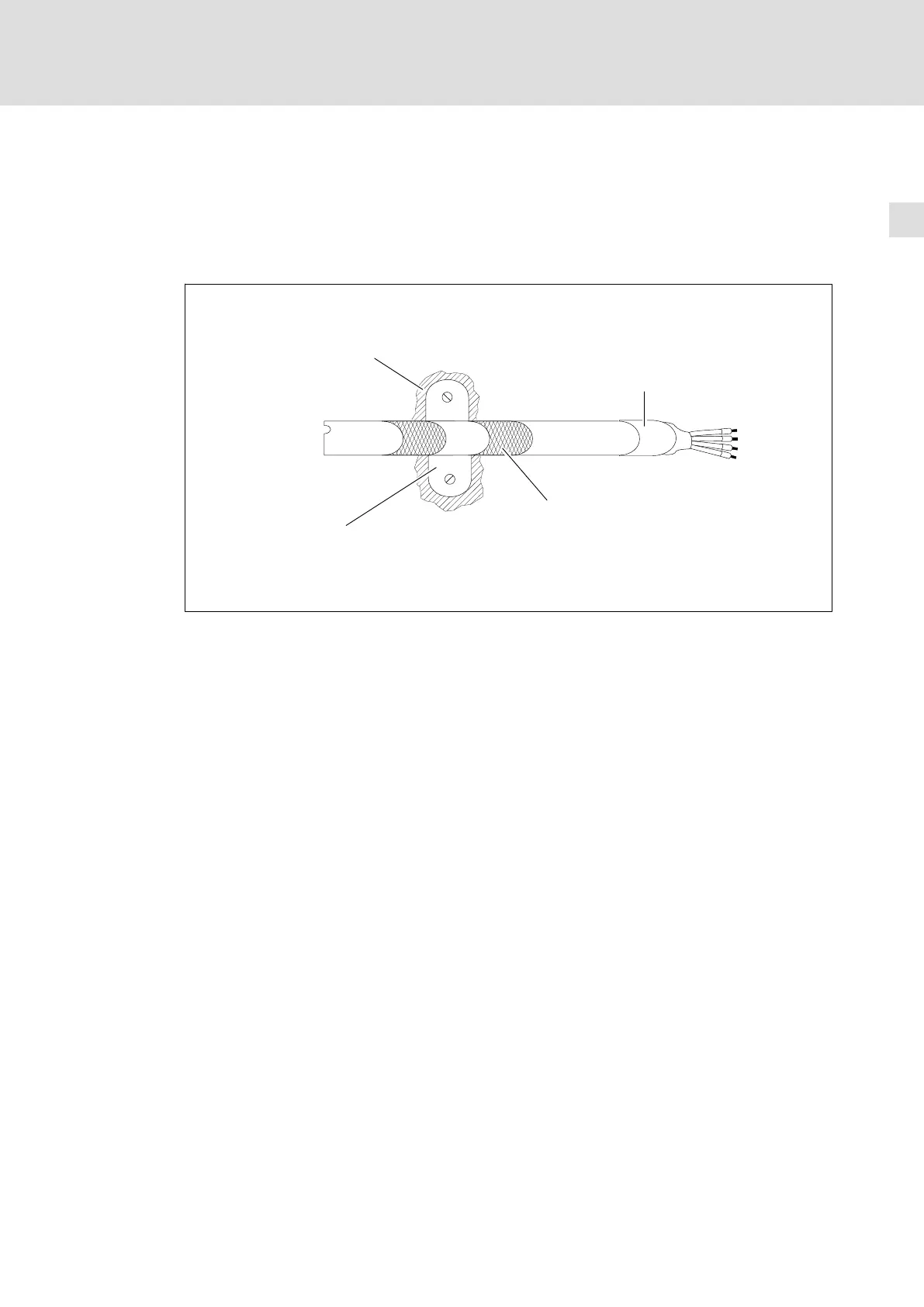
Shield connection system
ƒ Use an appropriate clip to connect the shield to the conductive mounting plate of
the control cabinet.
ƒ The connection should be as close to the cable end as possible.
ƒ If possible, cover the shield end with a shrink tube.
Remove
lacquer
Large−surface contact
of the cable shield
Shrink tube
Braid
Fig. 5−2 Shield connection
Carefully connect shields, ground connections (GND), and earth potential connections (PE)
to avoid interferences:
ƒ Do not interrupt shielding.
ƒ If an interruption cannot be avoided:
– Connect the shields at interruptions (terminal strips, relays, fuses) with a large
surface and both ends to the mounting plate.
ƒ The cables must be laid as close as possible to the reference potential (dangling
cables are like antennas).
Earthing
Ensure a good equipotential bonding of all system parts (934x regenerative power supply
module, controller, mains filter etc.) by cables to a central earthing point (PE bar). The
minimum cross−sections of the cables must be strictly observed.
Filtering
ƒ Only use the filters assigned to the regenerative power supply module :
– Mains filters reduce non−permissible high−frequency interferences to permissible
values.
 Loading...


