Electrical installation
Circuit proposals
Controlled shutdown of the drive system
5
126
EDBMB9340 DE/EN/FR 12.0
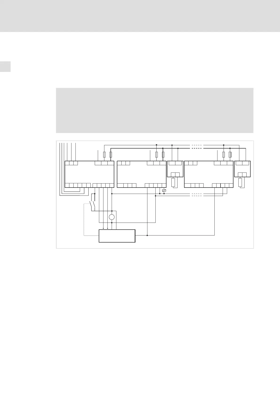
5.5.2 Controlled shutdown of the drive system
For controlled shutdown of the drive network additional 935X brake choppers have to be
installed in the network.
The same circuit principle can be used if more braking energy than permissible in the
feedback operation is to be dissipated.
Stop!
The regenerative power supply module may be destroyed if the feedback
operation of the regenerative power supply module and the brake chopper are
active at the same time.
For this reason, the circuit must be arranged so that the feedback operation
will be inhibited when the DC−bus voltage reaches impermissible values.
PE
U
VW PE
U
VW
L1 L1 L1L2 L2 L2
L3 L3 L3
+UG -UG
R
B
935x
+UG -UG
R
B
935x
24VDC
K10
39
Ex Ex28 28
Ax
K10
59 39
Ax
59
E1
39
A1 A2
59
934x
Z2.1
Z4
Z2.n
PE PE PE
+UG +UG +UG-UG -UG -UG
F4
F6 F8F5
F7 F9
_
+
=
FAIL
L3’
L2’ L1’
L3.2
L2.2L1.2
9340vrm009
Fig. 5−14 Circuit proposal − controlled shutdown of the drive system
934X Regenerative power supply module
Z2.1 ... Z2.n Controllers in the drive system
935x Brake chopper with brake resistor
Z4 Higher−level control (PLC, PC)
K10 Signalling relay "DC bus voltage too high"
F4...F9 DC−bus fuses
 Loading...


