Electrical installation
Regenerative power supply modules EMB9341 and EMB9342
Control connections
5
114
EDBMB9340 DE/EN/FR 12.0
5.3.2 Control connections
Terminal assignment
A1 A2
59
39
22 k
50 mA
50 mA
934x
E1
3 K
10 R
V > 30 V
R
9340vrm007
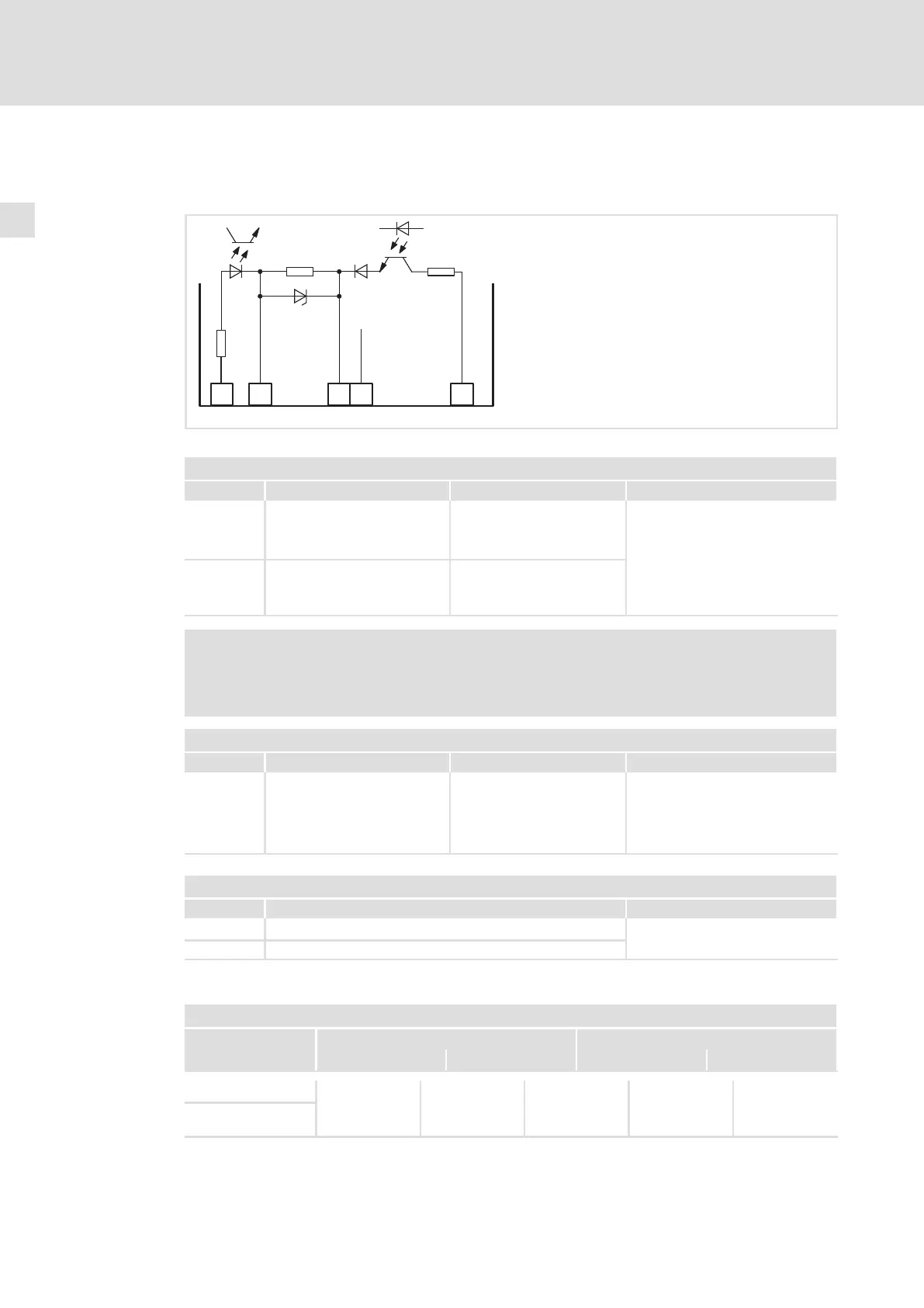
Fig. 5−6 Digital inputs and outputs
Digital outputs
Terminal Use Level with activated output Data
X2/A1 General fault indication LOW
LOW level: 0 ... +5 V
HIGH level: +11 ... +30 V
Short−circuit−proof
Output current:
max. 50 mA per output
(external resistance > 480 Ohm
with 24 V)
X2/A2 Mains failure LOW
Note!
Integrate terminal X2/A1 and X2/A2 into the release cascade of the drive
system.
Digital inputs
Terminal Use Level with activated input Data
X2/E1 Inhibit feedback operation HIGH LOW level: 0 ... +5 V
HIGH level: +11 ... +30 V
Input current with 24 V: 8mA
Reading and processing of the
input: once per 1 ms (average)
Voltage supply
Terminal Use Data
X2/39 Reference potential for terminal 59
DC 24 V, min. 100 mA
X2/59 Connection of the supply voltage for the digital outputs
Screw terminal data
Terminal data
Conductor cross−section Tightening torque
[mm
2
] [AWG] [Nm] [lb−in]
Flexible
2.5
12 0.5 ... 0.6 4.5 ... 5.3 PZ0
With wire end
ferrule
 Loading...


