Mechanical installation
Regenerative power supply modules EMB9341 and EMB9342
Mounting of EMB9341−E / EMB9342−E with "push−through" technique
4
93
EDBMB9340 DE/EN/FR 12.0
4.2.3 Mounting of EMB9341−E / EMB9342−E with "push−through" technique
In order to reduce the heat generation in the control cabinet, the heatsink of the
regenerative power supply modules EMB9341−E and EMB9342−E can be mounted outside
the control cabinet. Therefore, a mounting frame with seal (accessories) is required.
ƒ Distribution of the power loss:
– approx. 65 % by separated cooler (heatsink and blower)
– approx. 35 % inside the regenerative power supply
ƒ The rated data remain valid.
Dimensions
e
f
d1
d1
d
b1
b
c
c1
a1
a
g
> 100 mm
> 100 mm
9340vrm015
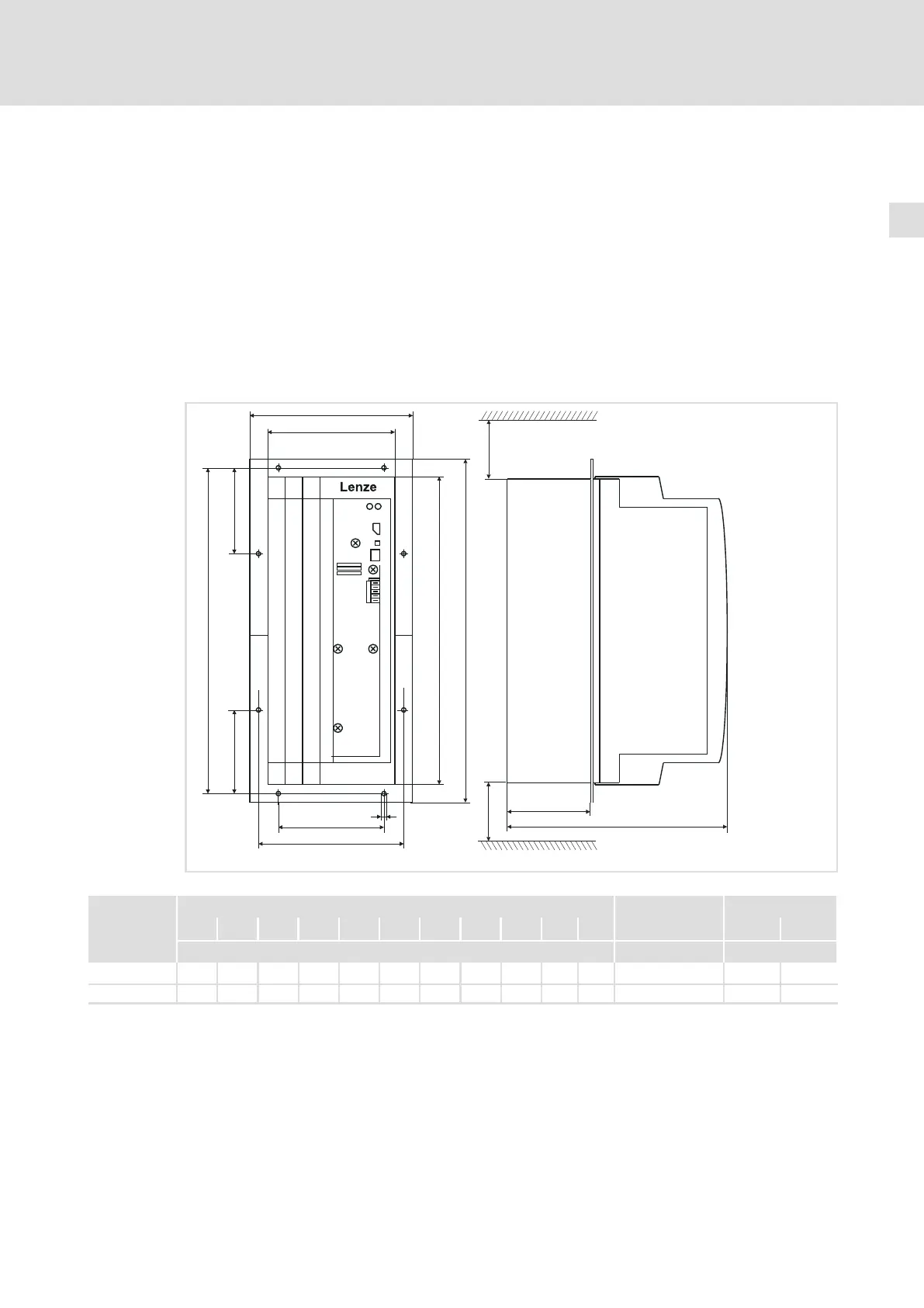
Fig. 4−4 Dimensions of EMB9341−E and EMB9342−E for mounting in push−through technique
Dimensions of regenerative power supply module Assembly frame Mounting cutout
a a1 b b1 c c1 d d1 e f g Order no. Height Width
[mm] [mm]
EMB9341−E 169.5 135 385.5 350 117 152.5 366 105.5 250 92 6.5 EJ0038 350 ±3 139 ±3
EMB9342−E 169.5 135 385.5 350 117 152.5 366 105.5 250 92 6.5 EJ0038 350 ±3 139 ±3
 Loading...


