Electrical installation
Regenerative power supply modules EMB9341 and EMB9342
Power connections
5
111
EDBMB9340 DE/EN/FR 12.0
39
28
Ax
59 39
28
Ax
59
M
3~
PE
M
3~
PE
E1
39
A1 A2
59
L3
N
PE
L1
L2
F1...F3
9341
9342
Z2.1 Z2.n
PE PE
+UG +UG +UG-UG -UG -UG
K1
F4
F6 F8F5
F7 F9
Z1
PE
U
VW PE
U
VW
L1 L1 L1L2 L2 L2
L3 L3 L3
L3’
L2’ L1’
L3.2
L2.2L1.2
L1
L1'
L2
L2'
L3
L3'
PE
PE
PE
9340vrm005b
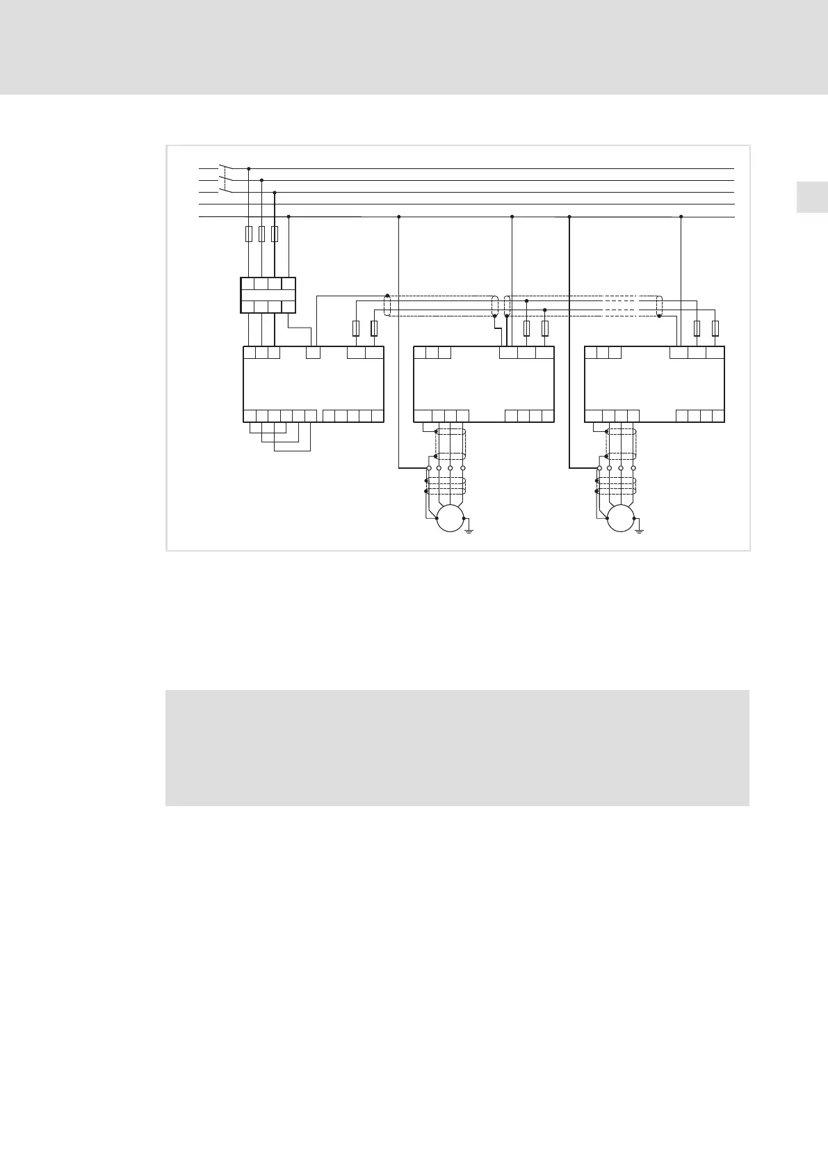
Fig. 5−4 Central supply for DC bus connection of several drives and internal mains synchronisation
Z1
Mains filter A
Z2.1 ... Z2.n Controllers in the drive system
F1...F3 Mains fuse
K1 Main contactor
F4...F9 DC−bus fuses
Wiring
Stop!
ƒ The PE connection and the shield sheet at the regenerative power supply
module must always be mounted in the sequence shown. The parts
required are included in the accessory kit.
ƒ Do not use the clips for strain relief.
 Loading...


