Parameterising analog modules
Parameter data
12
Parameter setting
12.3
12.3.1
l
12.3-3
EDSPM-TXXX-3.0-04/2004
Via the parameter data of the 4xanalog output module you can define the
following:
z
The signal function for each output (current signal output, voltage signal
output)
z
The module error behaviour
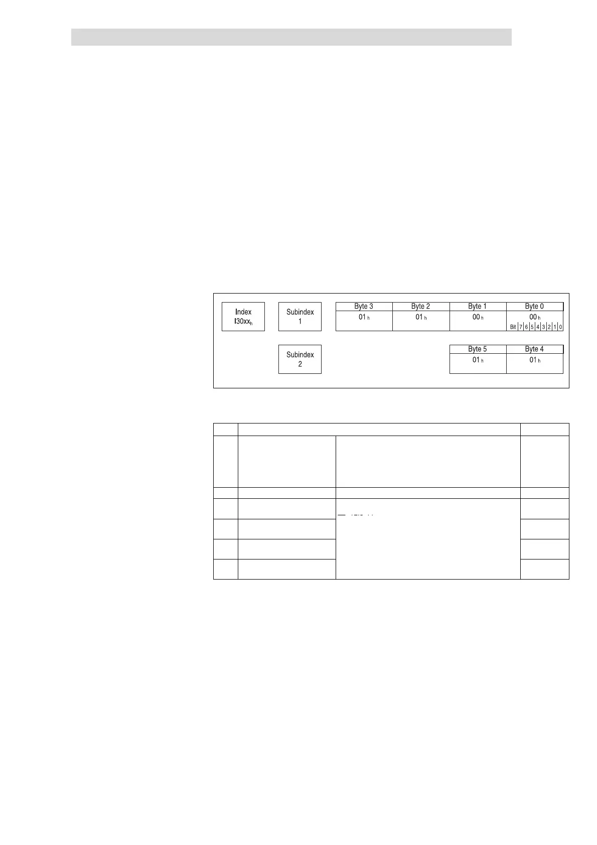
For the 4xanalog output 6 bytes of parameter data are available, which are
assigned via SDOs.
Depending on the plug-in station, the module is activated via the indices
I3001
h
... I3010
h
(max. 16 analog modules). The parameter data are assigned in
the subindex 1 ... 2.
epm-t193
Fig. 12.3-2 Display of the parameter data 4xanalog output
The following bytes with fixed assignment are available for parameter data:
Byte Assignment Lenze setting
0 Enabling / inhibiting diagnostic
Bits 0 ... 5 Reserved
00
h
alarm
1)
Bit 6
0 Alarm inhibited
1 Alarm enabled
E 12.3-6
0 Activating / inhibi ting
diagnostics
Bit 7 Reserved
1 reserved
2 Se l e cting signal function for
output E.0
Selecting the si gnal function for analog outputs:
E 12.3-11
01
h
3 Se l e cting signal function for
output E.1
01
h
4 Se l e cting signal function for
output E.2
01
h
5 Se l e cting signal function for
output E.3
01
h
1)
If the diagnostic al arm is e nabled, dia gnostic data are transmitted to the master via the emergency telegram in
the event of an error.
4xanalog output
 Loading...