16×dig. I/O compact (single-wire conductor)
6
The compact system
6.3
l
6.3-6
EDSPM-TXXX-3.0-04/2004
X4/1
X4/2
X3/10
X3/9
X3/8
X3/7
X3/6
X3/5
X3/4
X3/3
X3/2
X3/1
X4/3
X4/4
X4/5
X5/6
X4/7
X4/8
X4/9
X4/10
Z
Z
Z
Z
Z
Z
+
–
X1PE
µC
+
+
+
–
+
DC 24 V
(DC +18 … +35 V)
0
epm-t052
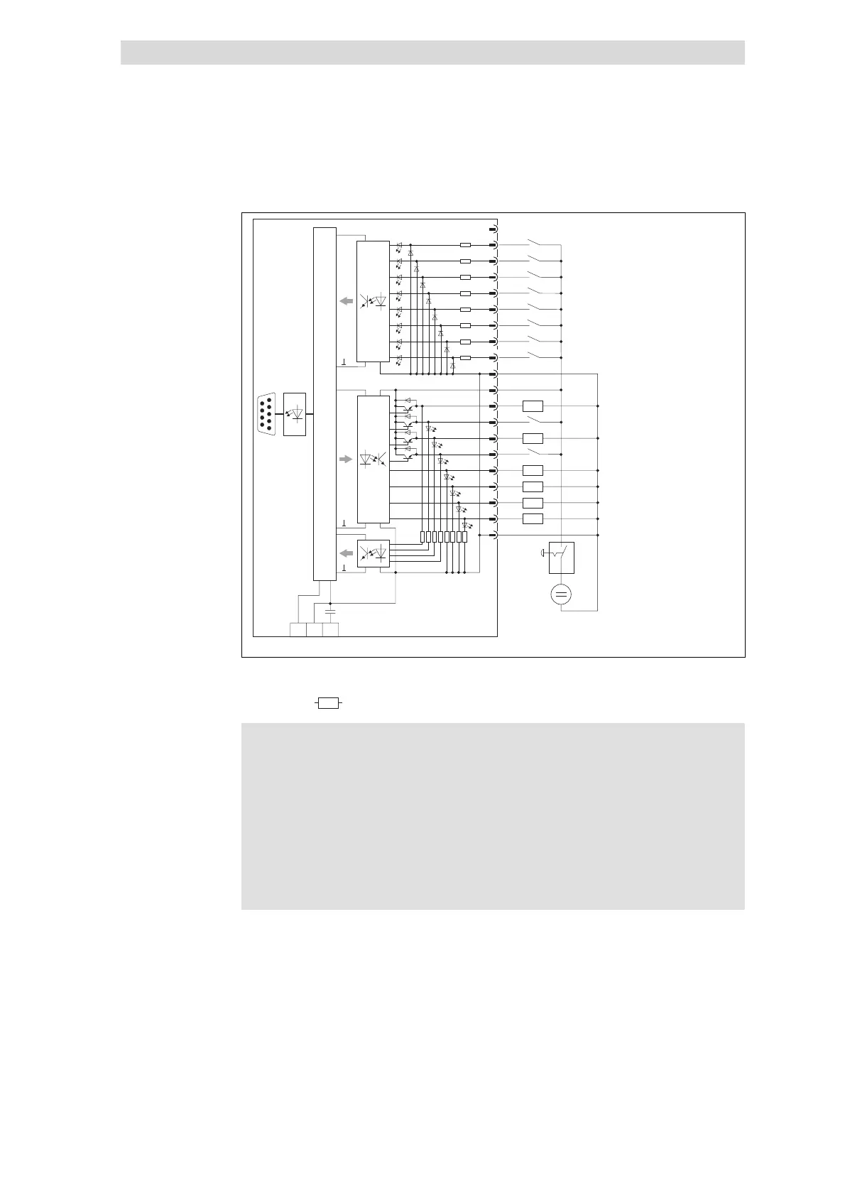
Fig. 6.3-5 Wiring diagram of 16×dig. I/O compact (single-wire conductor)
Emergency-off switch
Z
Load
Stop!
If the voltage supply (DC 24 V) fails, the module will malfunction:
z
Switched outputs carry voltage if one input is assigned with a
HIGH level,
z
Themodulecanbedestroyedsincetheoutputsarenot
resistant to short circuits anymore.
The emergency-off switch ensures that when being operated the
outputs do not carry any voltage and the inputs are not assigned
with a HIGH level.
Connection