Parameterising 2/4xcounter module
Measuring the frequency (modes 16 and 18)
12
Parameter setting
12.4
12.4.9
l
12.4-22
EDSPM-TXXX-3.0-04/2004
12.4.9 Measuring the frequency (modes 16 and 18)
1
2
3
4
5
6
7
8
9
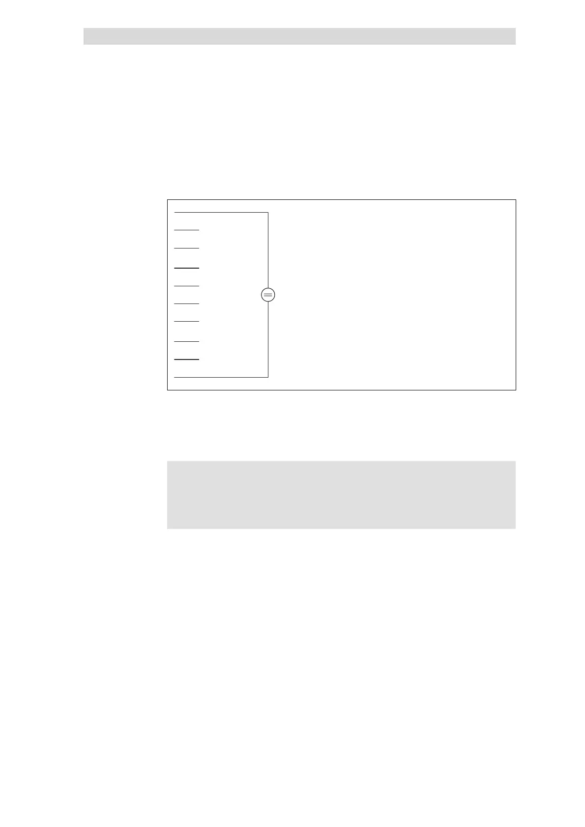
10 GND
+24VDC
In1 (RES)
In2 (CLK)
In3 (START)
Out0
In4 (STOP)
n.c.
n.c.
Out1
epm-t087
Fig. 12.4-29 Terminal assignment of the 2/4xcounter in the modes 16 and 18
Modes 16 and 18 allow determination of the frequency of a signal at input IN2
(CLK).
The modes differ in triggering the output Out0 / Out1 in different ways.
Note!
For measuring the frequency the counter 0 and 1 are required. For
this, both counters must be parameterised to mode 16 or 18.
Different modes cannot be set.
With the PDO byte 7 (Data In)a reference frequency (f
ref
) is transmitted to counter
0(seefigure”counter access”). The number ”n” of the reference frequency pulses
determines the gate time (period of time the counter 1 is to be released). ”n” can
be between 1 and 2
32
-1 and is loaded into the compare register.
A LOW-HIGH edge at input IN1 (RES) sets the counter to zero.
A LOW-HIGH edge at input IN3 (START) starts the measuring process.
During the measuring process the counter 0 counts with the first LOW-HIGH edge
at the input IN2 (CLK) the pulses ”n” of the reference frequency. Simultaneously
the counter 1 counts every LOW-HIGH edge at the input IN2 (CLK).
Both counters are stopped when
z
the counter 0 reading reaches the Compare value, or
z
input IN4 (STOP) receives a HIGH signal.
Terminal assignment
RES signal
START signal
CLK signal
STOP signal