Parameterising 1xcounter/16xdigital input module
32 bit counter with clock up/down evaluation (mode 2)
12
Parameter setting
12.6
12.6.5
l
12.6-9
EDSPM-TXXX-3.0-04/2004
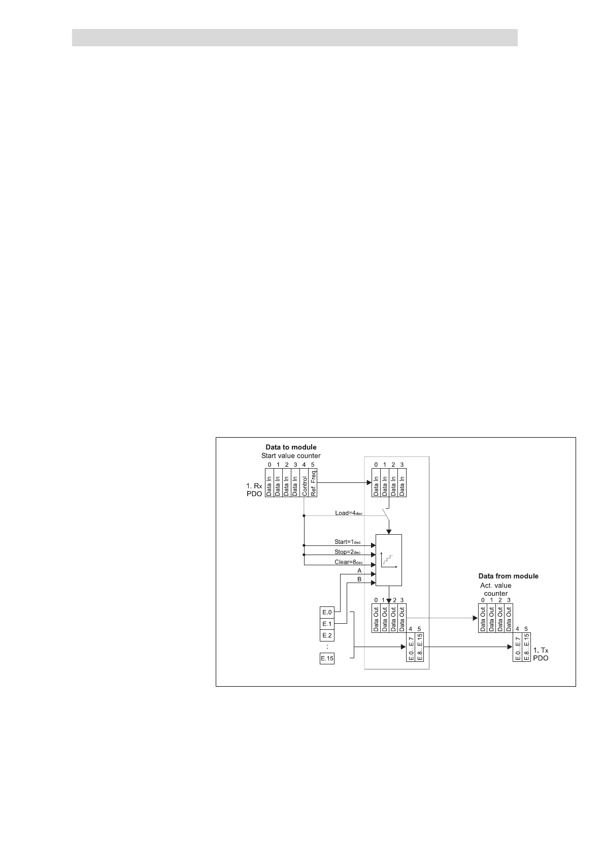
12.6.5 32 bit counter with clock up/down evaluation (mode 2)
In the mode 1 the counter operates as a clock-up/clock-down counter. The
counter can be pre-assigned with a starting value via the Rx PDO.
The counting range lies between 0 and +4.294.967.295. As soon as the upper limit
(when counting upwards) has been reached, the count value jumps to the lower
count limit. The moment, the lower count limit (when counting downwards) has
been reached, the count value jumps to the upper count limit.
A HIGH level in byte 4 (Control), bit 3 (Clear) sets the counter to zero.
When bit 2 (Load) changes from LOW to HIGH in byte 4 (Control), the counter is
pre-assigned with the starting value from byte 0 to 3 (Data In).
The software gate which releases the counting process, is opened, when bit 0
(Start) in the byte 4 (Control)has HIGH level. It is closed as soon as bit 1 (Stop)has
HIGH level.
With the software gate open: With every rising edge of the signal A (E.0)the counter
is incremented by 1. With every rising edge of the signal B (E.1) the counter is
decremented by 1.
epm-t177
Fig. 12.6-10 Counter access of 1xcounter/16xdigital input in the mode 2
Clear signal
Load signal
Start/ stop signal
A/ B signal
Counter access
 Loading...