16×digital input
5
The modular system
5.4
l
5.4-2
EDSPM-TXXX-3.0-04/2004
DI 16xDC24V
EPM – T211
1
2.0
3.1
4.2
5.3
6.4
7.5
8.6
9.7
10.0
11.1
12.2
13.3
14.4
15.5
16.6
17.7
18
0
1
+
–
1
2
3
4
14
15
16
17
18
DC 24 V (DC 18 … 28.8 V)
.
epm-t125 epm-t121
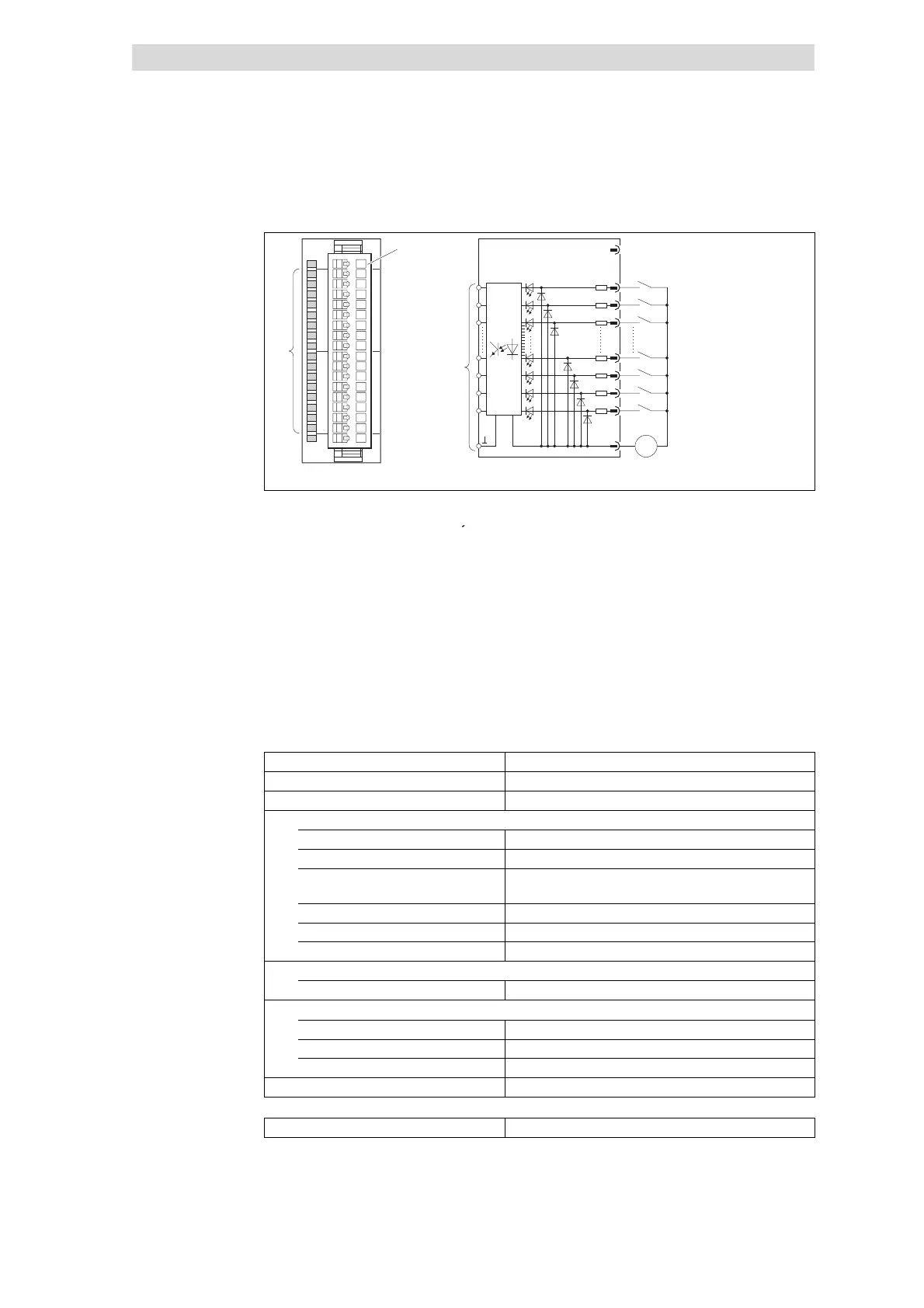
Fig. 5.4-2 Front view and connection of 16×digital input
2 × status display .0 ... .7; LED
Terminal strip assignment details
(green) is lit when a HIGH level is
1 Not assigned
eco
n
se
2 Digital input E.0
3 Digital input E.1
4 Digital input E.2
... ...
14 Digital input E.12
15 Digital input E.13
16 Digital input E.14
17 Digital input E.15
18 GND (reference potential)
)
Connection to backplane bus
Type
16×digital input
Voltage supply DC 5 V / 30 mA (via backplane bus)
Connectable cable cross-section ≤ 1.5 mm
2
(≥ AWG 16)
Digital inputs
Rated input voltage DC 24 V (DC 18 ... 28.8 V)
Number of i nputs 16
Level LOW: DC 0 ... 5 V
HIGH: DC 15 ... 30 V
Input resistance 3.3 kΩ
Delay time 3ms
Electrical isolation from backplane bus Yes, via optocouplers
Communication
Input data 2bytes
Dimensions
Width 25.4 mm
Height 76.0 mm
Depth 76.0 mm
Weight 50 g
Order designation EPM-T211
Status display and terminal
assignment
Technical data
 Loading...