8×digital output 2A
5
The modular system
5.7
l
5.7-2
EDSPM-TXXX-3.0-04/2004
DO 8xDC24V 1A
.0
L+
.1
.2
.3
.4
.5
.6
.7
F
1
2
3
4
5
6
7
8
9
L
10
EPM – T220 1A
1
2
0
3
1
2
3
4
5
6
7
8
9
10
.
–
+
Z
Z
Z
Z
Z
Z
Z
Z
DC 24 V (DC 18 … 35 V)
epm-t017 epm-t016
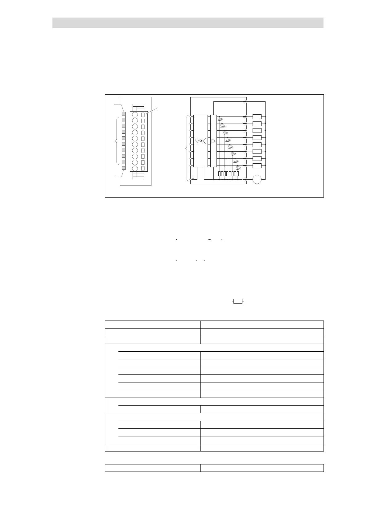
Fig. 5.7-2 Front view and connection of 8×digital output 2A
Status display L+; LED (yellow) is lit
when a supply voltage is applied
Terminal strip assignment
details
1 DC 24 V supply voltage
2 Digital output A.0
Status display .0 ... .7; LED (green) is
3 Digital output A.1
lit when the corresponding output is
4 Digital output A.2
t
e
e
5 Digital output A.3
Status display F; LED (red) is lit in
6 Digital output A.4
case of overload, overheating or
7 Digital output A.5
s
o
tc
cu
t
8 Digital output A.6
9 Digital output A.7
10 GND (reference potential)
)
Connection to backplane bus
Z
Load
Type
8×digital output 2A
Voltage supply DC 5 V / 20 mA (via backplane bus)
Connectable cable cross-section ≤ 2.5 mm
2
(≥ AWG 14)
Digital output data
Rated load voltage DC 24 V (DC 18 ... 35 V)
Number of outputs 8
Max. output current per output 2 A (sustained short-circuit-proof)
Max. output summation current 10A
Delay time <1ms
Electrical isolation from backplane bus Yes, via optocouplers
Communication
Output data 1byte
Dimensions
Width 25.4 mm
Height 76.0 mm
Depth 76.0 mm
Weight 50 g
Order designation EPM-T221
Status display and terminal
assignment
Technical data
 Loading...