4×relay
5
The modular system
5.8
l
5.8-2
EDSPM-TXXX-3.0-04/2004
DO 4xRELAIS
.0
.1
.2
.3
1
2
3
4
5
6
7
8
9
L
10
EPM – T222 1A
0
1
1
+5 V
2
3
4
5
6
7
8
9
10
.
Z
Z
Z
Z
epm-t020 epm-t021
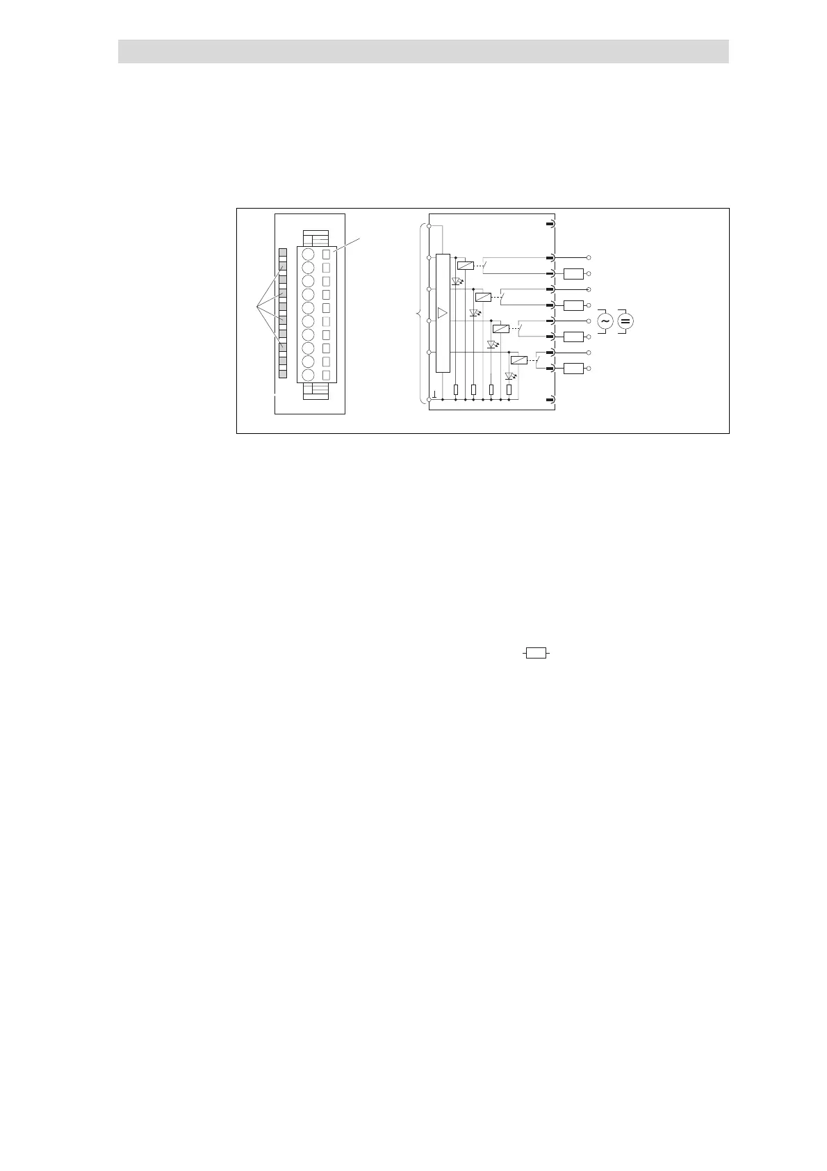
Fig. 5.8-2 Front view and connection of 4×relay
Status display; LED (green) is lit when
a relay output is triggered
Terminal strip assignment
details
1 Not assigned
2/3 Relay output A.0
.0 Relay output A.0 4/5 Relay output A.1
1. Relay output A.1 6/7 Relay output A.2
.2 Relay output A.2 8/9 Relay output A.3
.3 Relay output A.3 10 Not assigned
)
Connection to backplane bus
c External AC voltage source
AC 0 ... 230 V
d External DC voltage source
DC 0 ... +30 V
Z
Load
Status display and terminal
assignment