2/4×counter
5
The modular system
5.13
l
5.13-2
EDSPM-TXXX-3.0-04/2004
2 Counter 2 DO
R0
C0
D0
O0
R1
C1
D1
O1
F
L+
1
2
3
4
5
6
7
8
9
L
10
EPM – T410 1A 10
0
1
2
3
4
2
C0
C2
1
OUT0
OUT1
GND
IN1
IN4
IN3
IN6
IN2
IN5
3
5
7
9
10
4
6
8
.
+
–
DC 24 V
(DC 18
… 30 V)
Z
Z
epm-t038 epm-t039
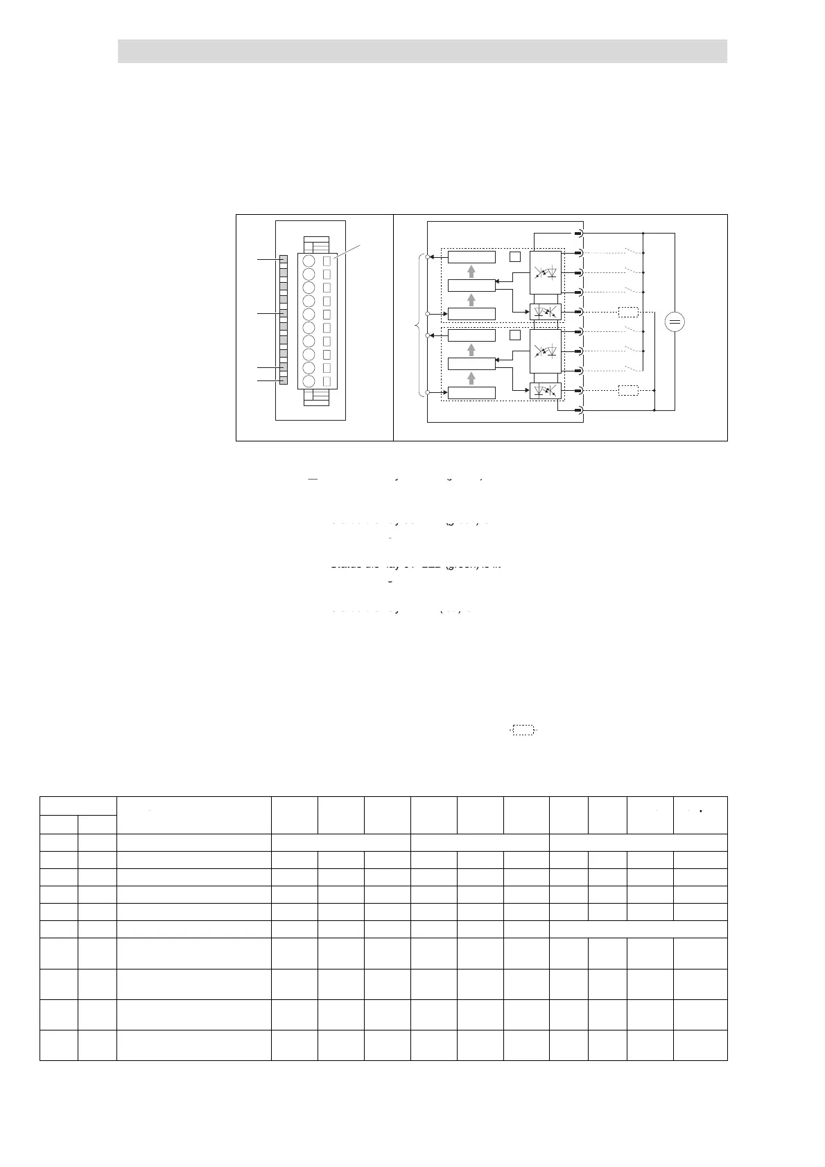
Fig. 5.13-2 Front view and connection of 2/4×counter
Status display L+; LED (yellow) is
Terminal strip assignment details
lit when a supply voltage is applied
1 DC 24 V supply voltage
2 IN1: Input 1 of counter 0
Status display 00; LED (green) is lit 3 IN2: Input 2 of counter 0
when the digital output OUT0 is
4 IN3: Input 3 of counter 0
triggered by counter 0
5 OUT0: Counter 0 output
Status display 01; LED (green) is lit 6 IN4: Input 1 of counter 1
when the digital output OUT1 is
7 IN5: Input 2 of counter 1
triggered by counter 1
8 IN6: Input 3 of counter 1
Status display F; LED (red) is lit in 9 OUT1: Counter 1 output
case of overload, overheating, and
short circuit
10 GND (reference potential for
supply voltage)
)
Connection to backplane bus
C0 32-bit counter 0
c1 32-bit counter 1
c Buffer
d Counter register
Z
Load
Counter mode overview
Mode of
Function IN1 IN2 IN3 IN4 IN5 IN6 OUT0 OUT1 Auto
Compare
[h] [dec]
Reload
Load
2 counters 0 1
00
h
0 32-bit counter RES CLK DIR RES CLK DIR • • – –
01
h
1 Encoder 1 edge RES A B RES A B • • – –
03
h
3 Encoder 2 edges RES A B RES A B • • – –
05
h
5 Encoder 4 edges RES A B RES A B • • – –
4 counters 0.1 0.2 1.1 1.2
08
h
8 2 × 16-bit counters
(counting direction up/up)
– CLK CLK – CLK CLK – – – –
09
h
9 2 × 16-bit counters
(counting direction down/up)
– CLK CLK – CLK CLK – – – –
0A
h
10 2 × 16-bit counters
(counting direction up/down)
– CLK CLK – CLK CLK – – – –
0B
h
11 2 × 16-bit counters
(counting direction down/down)
– CLK CLK – CLK CLK – – – –
Status display and terminal
assignment
 Loading...