SSI interface
5
The modular system
5.14
l
5.14-2
EDSPM-TXXX-3.0-04/2004
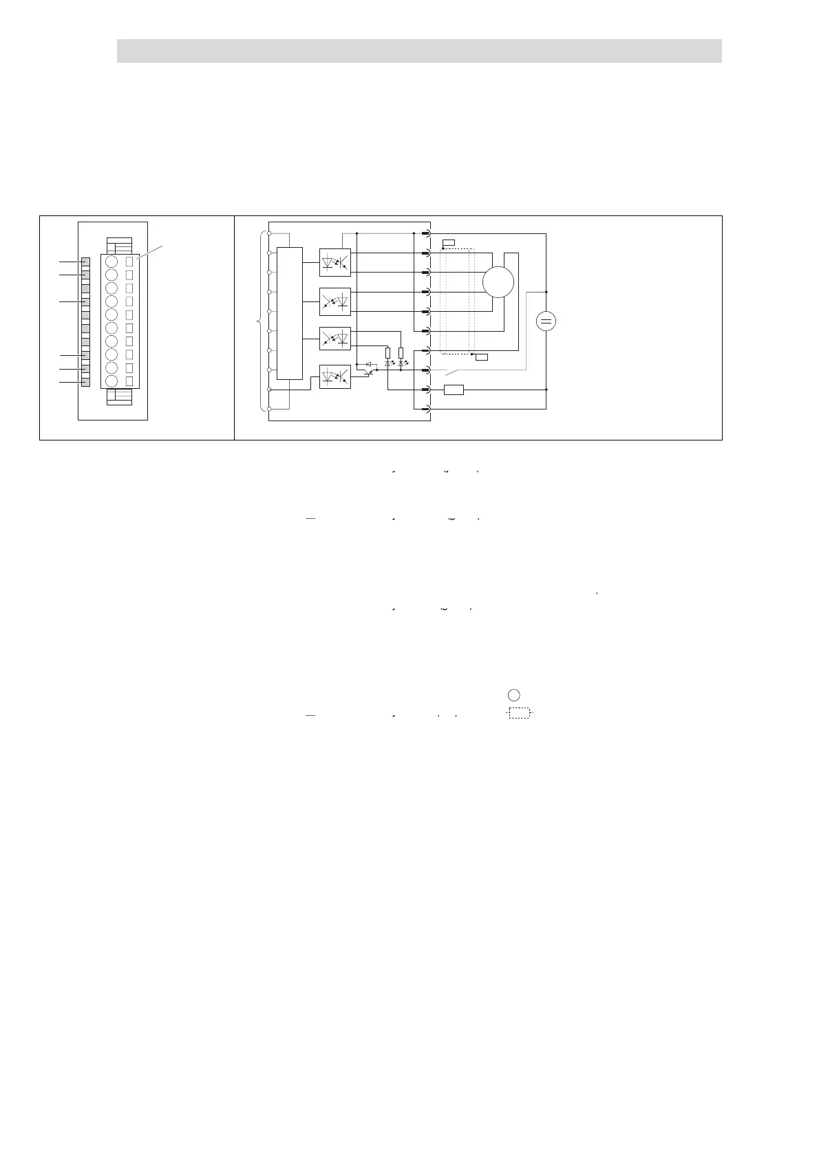
Status display and terminal assignment
SSI
Cl+
Cl-
D+
D-
Us
M
.0
.1
F
L+
1
2
3
4
5
6
7
8
9
L
10
EPM – T411 1A. 10
0
1
2
3
4
5
6
.
2
1
3
5
7
9
10
4
6
8
PES
PES
–
–
+
+
DC 24 V
(DC 18
… 28.8 V)
µP
Z
SSI
epm-t124 epm-t130
Fig. 5.14-2 Front view and connection of SSI interface
Status display L+; LED (yellow) is
Terminal strip assignment details
lit when a supply voltage is applied
1 DC 24 V supply voltage
2 Clock pulse
Status display Cl+; LED (green) is
3 Clock pulse converted
lit with an output clock signal
4Data
5 Data converted
Status display D+; LED (green) is lit
when the SSI sensor is receiving
6 DC 24 V supply voltage for
SSI sensor
data
7 GND (reference potential of
Status display .0; LED (green) is lit
supply voltage for SSI sensor)
when a HIGH level is applied to or
p
p
p
8 Input/output .0
output at
nput
output .0
9 Input/output .1
Status display .1; LED (green) is lit
when a HIGH level is applied to or
10 GND (reference potential for
supply voltage)
output at input/output .1
)
Connection to backplane bus
SSI
SSI sensor
Status display F; LED (red) is lit
Z
Load
when the inputs / outputs .0 or .1
a
es
o
t-c
cu
te
o
ove
oa
e