8400 BaseLine D | Software Manual
I/O terminals
Digital outputs
118 L Firmware 03.00 - DMS EN 5.0 - 07/2009
6.3 Digital outputs
The controller is provided with a parameterisable digital output and a relay output.
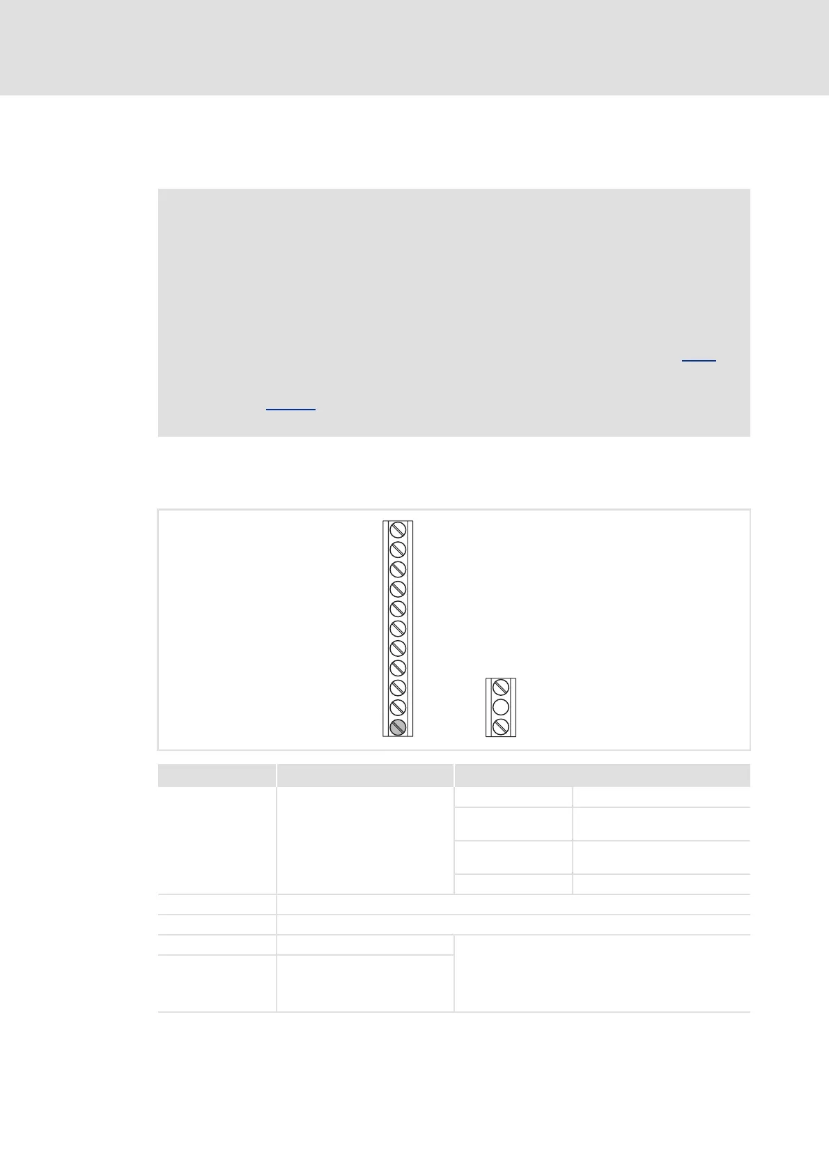
6.3.1 Terminal assignment/electrical data
Note!
Initialisation behaviour:
• After mains switching up to the start of the application, the digital output
remains set to FALSE.
Exception handling:
• In case of a critical exception in the application (e.g. reset), the digital output
is set to FALSE considering the functional direction parameterised in C118
.
Switching cycle diagnostics:
•Code C177/2
serves to evaluate the load of the relay by querying the
switching cycles.
Terminal Use Electrical data
X4/DO1 Digital output 1 LOW level: 0 V
HIGH level: +12 ... +30 V (independent of the
voltage at X4/24E)
Output current: max. 50 mA (external resistance
> 480 Ω at 24 V)
Processing cycle: 1 ms
X4/24E External voltage (24 V DC) to supply the digital output
X4/GND Reference potential (digital ground)
X101/COM Relay output, common contact Potential-free two-way switch
AC 250 V / 3 A
DC 24 V / 2 A ... 240 V / 0.16 A (with suppressor circuit)
Important: The minimum load must not fall below 12 V
and 5 mA.
X101/NO Relay output, NC contact
X4
24E
DO1
GND
A1U
AR
12I
RFR
DI1
DI2
DI3
DI4
X101
NO
COM
 Loading...