20 – Control CS 320 / Rev.D 1.01 Control CS 320 / Rev.D 1.01 – 21
EN
NOTE:
Withrstcommissioningandafterareset,input2issettoA
(self-teaching) once.
If a resistance value is detected, MOD2 (safety input) is
automatically set and the measured value is stored and
monitored as a reference for the connected safety-related
components.
Deviation of the measured value leads to an error message.
If a safety element is subsequently added or removed, the
resistance measurement must be performed again. For this
purpose the parameter INPUT 2 must be manually reset to A
(self-teaching) and the supply voltage must be switched off
and on again once. Renewed measurement then takes place.
The components used must either comply with EN ISO 13849-1
PLc/Cat.2 or be approved as a reliable component in order to
satisfytherequirementsofEN12453:2017.
Alternatively, the fall protection can also be equipped with an
NC contact and integrated in the safety circuit of the
controller (X3/1-2). This switch with NC contact must be
approved as a reliable component per
EN ISO 13849-1. To ensure cross-wire short monitoring, the
connection cable must be laid in a protective tube.
5.15 Radio receiver, pluggable
2 different pluggable radio receivers can be connected to the
controller directly.
CS-radio 1-channel, multi-bit, 15 storage spaces
− 868MHz-art.no.76616
− 433MHz-art.no.76614
Compatible hand-held transmitter:
− RT 52, 28, 29, 31
− Digital 382, 384, 313, 321, 323, 306, 318
Digital 991 1-channel, AES 128 Bit, 200 storage
spaces
− 868MHz-art.no.118726
− 433MHz-art.no.118727
Compatible hand-held transmitter:
− Digital 564, 663, 572, 633, 506, 517, 518
X9
5.15 / 1
B
A
C
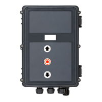
A Antenna
B Programming button
C LED
REFERENCE
For a precise description of the function and connection,
refer to the separate documentation for the radio receiver.